Hey guys:
I am a newbie to audio so here is my stupid question
I am building a stereo power amplifier with TDA2030, in bridged mode, powered by a modified +-14V computer SMPS (i have completely modified the output line of the -12V line to allow it to sink a large amount of current)
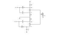
the power amplifier's schematics is:
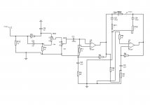
however I would like to add a tone control to the amplifier too, and this is the circuit diagram
Would it work if I connect my source (cellphone's output, abt 1V peak to peak, I think) to the tone control circuit and then to the input of the TDA2030 amplifier? would the signal be strong enough to drive the chip at full power or do I need a pre amplifier in front or after the tone control to compensate for the tone control's lost (-20dB is what the simulator tells me)
thank you
I am a newbie to audio so here is my stupid question
I am building a stereo power amplifier with TDA2030, in bridged mode, powered by a modified +-14V computer SMPS (i have completely modified the output line of the -12V line to allow it to sink a large amount of current)
the power amplifier's schematics is:
An externally hosted image should be here but it was not working when we last tested it.
however I would like to add a tone control to the amplifier too, and this is the circuit diagram

Would it work if I connect my source (cellphone's output, abt 1V peak to peak, I think) to the tone control circuit and then to the input of the TDA2030 amplifier? would the signal be strong enough to drive the chip at full power or do I need a pre amplifier in front or after the tone control to compensate for the tone control's lost (-20dB is what the simulator tells me)
thank you
Well a Passive tone controll is going to drop quite a bit of voltage so there will be losses , I would suggest maybe a Make up gain stage either before or after the tone curcuit (I would put a buffer at the front and a make up gain stage at the end) ......
Tone circuits like the one you posted pretty much sound best with the Pot at 10 or without frequncy attenuation so to get a more robust versitile tone controll I would suggest an active 3 band tone controll , there are even some very simple to use eq/Tone controll IC"s , I recently did a 5 band Graphic with a BA3812 that actually sounds pretty good .....
Good luck
Change those 22K resistors to 47K, the additional 6dB gain should compensate for most of the loss.
The 2030 does not like being bridged, I can tell you that. It survives but the sound quality goes to pot. The current capability of the chip is very low, and it doesn't like sinking current at all. I'd be surprised if you got more than 30 clean watts out of it.
For cellphone output, it should do however, and the 47K/680 ohm combination should have sufficient gain from the signal for max output, tone control notwithstanding.
The LM1875 will fit that circuit just fine (I think it is even pin-compatible), though I don't about it bridged. For such a low voltage bridged is your only option for real power, though bridging puts a lot of stress on the output stage - I don't know about these little 3A chips cutting it.
I had bridged a set of 2030s for a stereo amp and it worked. The sound quality was not great and the chips ran terribly hot - I ran off a +/- 19V supply. If you're not super-critical about the sound quality you could go ahead and try.
The problem with your requirement and these chips is that you will get a maximum of 10V swing per output half, or 20V total. 20V into 8 ohm load is ~2.5A, with the 3-4A current limit of these chips you're running too close to the output maximum. Some back-of-envelope calculations show the output at about 50 watts, or 25 watts per chip. The chip's output rating is 22 watts. To make this work you will need 4 chips, or a different chip.
As much as I can from the available supply voltage, +-14V
In to a 8 ohm load
Well.if I were you, I would not use any tone controls.The fewer components in the signal...the better!.
The LM1875 will fit that circuit just fine (I think it is even pin-compatible), though I don't about it bridged. For such a low voltage bridged is your only option for real power, though bridging puts a lot of stress on the output stage - I don't know about these little 3A chips cutting it.
I had bridged a set of 2030s for a stereo amp and it worked. The sound quality was not great and the chips ran terribly hot - I ran off a +/- 19V supply. If you're not super-critical about the sound quality you could go ahead and try.
The problem with your requirement and these chips is that you will get a maximum of 10V swing per output half, or 20V total. 20V into 8 ohm load is ~2.5A, with the 3-4A current limit of these chips you're running too close to the output maximum. Some back-of-envelope calculations show the output at about 50 watts, or 25 watts per chip. The chip's output rating is 22 watts. To make this work you will need 4 chips, or a different chip.
I dont have to run the chip to full power, 40W is more than enough for my need. I will start building it next week, with LM1875 that is.
here is the circuit I worked out

its one channel, the tone control is connected straight to the LM1875 chips, which is powered by +-14V supply.
on the simulator it shows the amplifier can reach full power (+-24V at 500mV input level, with the volume control on full)
I was planning to start building it tomorrow, however my power supply just blew up in my face, so I would be going on computer PSU hunt again next week.
take a look at the tda2050/lm1875 discussion thread,
http://www.diyaudio.com/forums/chip-amps/155256-tda2030-vs-lm1875.html
the tda 2050 is 25watts into 8ohm and 32watts into 4ohm. if you bridge into 8ohm to get 50watts thats 25 per chip into 4ohms from the data sheet you would need +/- 15 volts. (at full input voltage!)
hope this helps, happy soldering, steve.
- Status
- This old topic is closed. If you want to reopen this topic, contact a moderator using the "Report Post" button.
- Home
- Amplifiers
- Chip Amps
- TDA2030 tone control