That is a great double triode. Have fun with it.
Hey man, thanks. Question: Would you look over the schematic at post 74 and do a sort of "fill in the blanks" for the LM3886 resistor values? The point (I think) is the least gain from LM3886 and the most gain from the tube, all within reason, of course.
All,
This project is taking on a life of its own. While going thru my junkbox I found a good size transformer. I think it is from an old Receiver. It has a secondary of 62VCT. It is of the size and shape that I "like" for my projects. I am thinking that from its size and weight it is good for about 300VA or so...maybe more. It would free up some real estate on the chassis for the tube complement to be added. I think I can Point to Point what is needed to get this together rather than purchase pre-built stuff. I am thinking that I can built a BRIDGE using Ultra Fast Recover Diodes on a piece of Perfboard for the PS. This is simple to do just use the center tap as 0V and +/- off the "bridge" correct? Should be about 40V =/- ??
Daniel,
6922 is I nice tube, where did you buy it and what did you pay?
I am not sure that you really need a tube with that high a Mu (amplification Factor).
What experience do you have with tubes? I can certainly be of help to you.
Running that tube at 90V on the plate with 12mA of current gives a Gain of about 33. That is a lot of gain unless your source is very weak.
I will explain the schematic from #74 shortly.
Let me look at 692 data sheet for a minute or two I can give you revised values for that tube.
What is the minimum gain that a 3886 likes in its circuit? That is why I left those values blank.
62vct + MUR860 will stick open one of the output transistors aboard LM3886 and output a steady 45vdc to the speaker after approximately 5 months time.
Long term testing suggests that max is 52vct transformer. And the heatsinks will be much less expensive--so much less expensive that the right size transformer is free (in comparison).
This is approximately the right size transformer for LM3886 stereo amp with dual bridge rectifiers: http://www.antekinc.com/details.php?p=79 28+28, 7a
And this is less expensive for single bridge or dual bridge rectifiers:
http://www.antekinc.com/details.php?p=53 25+25, 5a
Last edited:
To all,
This thread has officially been HIJACKED by myself (the OP) and has now become a collaborative effort (between myself & Daniel) to design a relatively simple TUBE/Gainclone Hybrid.
I will be adapting the design for my own needs but for the purposes of the project we will be looking at an outcome of:
40Watts/Channel @ 8Ohm load
Dual Triode input section
Relatively low voltage on the "tube" section to allow for easily sourced transformers.
Vacuum tube or SS rectification of the Tube B+
Other specs TBD
I am thinking that for the purposes of this project we want to look at the following tubes
12AU7
6CG7/6FQ7
6SN7 for a really "Vintage" look and the "Octal" Fans out there
These are relatively low "medium-mu" Dual Triodes (meaning one tube for both channels)
They will need roughly 150V @ 30-50mA's, so this can be easily done by placing two RatShack 12V Trannies "Back to Back" 120 to 12V then 12V to 120V and use a Bridge or Half Wave tube rectifier.
Without getting into the age old debate of Tube Rectification VS. Solid State I will offer the following suggestions as to the choice.
Solid State bridges are:
Cheap
Reliable
easy to wire
Allow for greater capacitance immediately following them
BUT,
They aren't TUBES
Sound a little too "tight", "Tinny" or "Bright"
Tube Rectifiers are
Smooth sounding
TUBES
Look like tubes
But,
Expensive
can be "noisy"
need a filament supply
harder to wire and design
For the sake of project simplicity I plan to design with SS Bridge rectification. Anyone interested in the tube rectification will most likely have the "know how" to design it and if they like I can help if needed.
One ideal in first class audio is to have the gain stage run either its own private transformer or on regulators. It avoids having the speaker slam the gain stage with high amperage noise.
In this case, we need to keep up with a "vacuum tube mids and treble amplifier" that was already a high dynamics build. Now freed of its bass duties, its fierce competition to the subwoofer amp.
This is quite similar to a purpose-made TDA7294 mids and treble amplifier run along with a purpose made LM3886 woofer amplifier. Illustration: Mids and treble fall from the heavens as if a snowstorm of music, and that might be terrible if the woofer amp didn't compete / hold up.
Thus, the subwoofer amp (woofer amp) must Not sink the voltage of its own gain stage.
P.S.
I think that others who have no interest in vacuum tubes may substitute "LM1875 Class A Heaphone Amp on Regulated Power" for some of the vacuum tubes, including the gain stage of the LM3886 subwoofer amp. Results should be similar, but the only way to know for sure is buy a vacuum tube. lol! I did!")
In this case, we need to keep up with a "vacuum tube mids and treble amplifier" that was already a high dynamics build. Now freed of its bass duties, its fierce competition to the subwoofer amp.
This is quite similar to a purpose-made TDA7294 mids and treble amplifier run along with a purpose made LM3886 woofer amplifier. Illustration: Mids and treble fall from the heavens as if a snowstorm of music, and that might be terrible if the woofer amp didn't compete / hold up.
Thus, the subwoofer amp (woofer amp) must Not sink the voltage of its own gain stage.
P.S.
I think that others who have no interest in vacuum tubes may substitute "LM1875 Class A Heaphone Amp on Regulated Power" for some of the vacuum tubes, including the gain stage of the LM3886 subwoofer amp. Results should be similar, but the only way to know for sure is buy a vacuum tube. lol! I did!
To all,
This thread has officially been HIJACKED by myself (the OP) and has now become a collaborative effort (between myself & Daniel) to design a relatively simple TUBE/Gainclone Hybrid.
We need the more experienced solid state designers too!! Their maths are as beautiful as any artists painting, and this pleases the electronics greatly.
Let's please do get as much input as possible from AndrewT and Ratza.
I try to pay attention as far as possible because happy electronics are much easier to deal with!
Lets please remember that its not audio science until both audiology and electronic engineering are done simultaneously.EXACTLY,
The plan would be for the two sections to be "discrete" ie; The tube will have its own PowerSupply and merely send its amplified signal to the chip amp via a coupling capacitor and ground. Ground in this case is purely a voltage reference for the signal so it would be the "signal ground" of the chip amp. The Rin of the chip amp would also function as the output impedance for the tube. A Cin would be sized accordingly to the value of this resistor. ie; it forms a first order High Pass filter. In my case I will set an F3 quite low (big cap) for mids-highs or smaller speakers you could size as appropriate.
The output impedance has an effect on the gain of the tube so we need to size this a little bigger than 10K (I think, will know more as I look at the tube specs).
I DEFINATELY welcome any help/ideas/criticism etc from the other members of the forum.
Consider this an "Open Source" forum and chime in anytime. Please PM if you have attachments so I can download and file them.
I am thinking that for the purposes of this project we want to look at the following tubes
12AU7
6CG7/6FQ7
6SN7 for a really "Vintage" look and the "Octal" Fans out there
These are relatively low "medium-mu" Dual Triodes (meaning one tube for both channels)
They will need roughly 150V @ 30-50mA's, so this can be easily done by placing two RatShack 12V Trannies "Back to Back" 120 to 12V then 12V to 120V and use a Bridge or Half Wave tube rectifier.
Without getting into the age old debate of Tube Rectification VS. Solid State I will offer the following suggestions as to the choice.
Solid State bridges are:
Cheap
Reliable
easy to wire
Allow for greater capacitance immediately following them
BUT,
They aren't TUBES
Sound a little too "tight", "Tinny" or "Bright"
. . .
While you're at the Radio Shack, their 6A05 diodes can make for an incredibly dull and inefficient bridge rectifier.
The "looks like fork" SCE KBU808 is the tinny and bright. May I suggest a simple bit of decency with 1n540x series for the gain stage? http://www.diodes.com/datasheets/ds28007.pdfAlso, it would be really nice to run the gain stage regulated, if possible.
What is the minimum gain that a 3886 likes in its circuit? That is why I left those values blank.
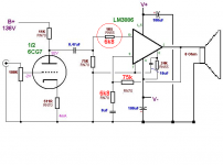
The minimum gain has to be 10 or bigger, according to the datasheet. I would use the tube as cathode follower and let the LM do the job.
daniel, for that circuit I would do it like in the image attached. The NFB cap has a reactance of 1mOhm at 20Hz, so it's big enough. The gain will be in this case
12 (21dB).
Attachments
Last edited:
Ebay, $20 to the door.. . .
6922 is I nice tube, where did you buy it and what did you pay?
For computer source a lot of gain is needed.I am not sure that you really need a tube with that high a Mu (amplification Factor).
A quick fix on one old A.M. radio, one explosion involving Johnny Cash plus a trip out a window for me, and the recent purchase of the Philips 6922 is the extent of my abilities with a vacuum tube. This purchase was mostly in the dark because a compact florescent had lost integrity at that very moment. Yes, I'll need help.What experience do you have with tubes? I can certainly be of help to you.
Computer sound is plagued with practically no drive, lots of compression (of several sorts) and amplifying it can sound like the roar of home theater or at least draw a lot of attention to the speakers whilst too distracting/failing to present a concert. To fix, this will require a high-gain amp that exaggerates dynamics. The pre-drive in particular needs to be capable of quite the shove.Running that tube at 90V on the plate with 12mA of current gives a Gain of about 33. That is a lot of gain unless your source is very weak.
. . .What is the minimum gain that a 3886 likes in its circuit? That is why I left those values blank.
From 3 in inverting mode. OH, you said "likes"
well that would be 10 in inverting mode. For non-inverting mode, we run into a bit of trouble with compensation. LM3886 doesn't have much. You can tell because its prone to screech the mids. Well, we don't need it for mids anyway. Nevertheless, I'd still like to see it run right and I cannot do it.
One option that should be documented, IMO, is that for a full-bandwidth amplifier, paralleling the LM3886 will turn that screech into heat, and I think that the heatsink is a better spot for that noise to go than the speaker.
In non-inverting mode, there's no amount of gain and no circuit that I know of which will fully compensate LM3886 unless it is run parallel to fight off its own noise. Thus, you can see that parallel mode is unlikely to reduce heat output. Now, if somebody smarter than I can run LM3886 properly compensated somehow, then lower gains are possible in non-inverting mode. Else, the answer is approximately 17.
Gain of 33+17 = 50. This is just fine for computer source--the high gain will help prevent limp audio.
The minimum gain has to be 10 or bigger, according to the datasheet. I would use the tube as cathode follower and let the LM do the job.
daniel, for that circuit I would do it like in the image attached. The NFB cap has a reactance of 1mOhm at 20Hz, so it's big enough. The gain will be in this case 12 (21dB).
Thank you!! This appears to be a non-inverting LM3886. Is that correct?
Last edited:
Two points
#1. Cathode Follower is less than Unity Gain, which means we need to use ALL of the available gain the Chip would have UNLESS
a: we use TWO tubes a Gain Stage and the follower.
or
b: No follower just a simple Resistance Coupled amp as drawn with some compromises on the gain.
2: In the tube world I tend to shy away from regulated supplies, in this case it is not really an issue because of the low currents needed, a Zener String could do it, or a Vacuum tube regulator can be used. The regulator tubes look real cool because they burn off the extra voltage as a "glow" inside the tube. They are really NOISY.
Lets all "AGREE" on the overall topology. Here's my .02 cents.
Inverting Chip amp with a gain somewhere around the 10 area? What would be "ideal" there maybe 12-15?
I say Inverting because the tube inverts the signal so we end up with an "in phase" output matching the output of the sound card.
If you are looking for an overall gain of 50 or so then we use the 6922, I prefer less gain because we end up amplifiying all the noise also. I will use a 6CG7 (that is my bottle head preference) but will help this project allong with the 6DJ8/6922/ECC88 specs since those are typical audiophile tubes.
I suggest that we use the simplest form of the tube amp. NO Solid State devices as CCS or anything, just a tube and four resistors. (one of which is "shared" with the chip)
I am also going to go out on a limb and specify we use about 110-120AC rectified to about 150DC for the plate supply. Any higher and we need large Plate/Load resistors and get more unwanted gain. I will draw up a 6922 Schematic with a simple Power Supply, you SOLID STATE gurus draw me up the power amp section with an imput impedance of 20K.
20k? The tube and the chipamp don't share a common ground. They only share a signal ground. Inverting or non-inverting doesn't seem important as long as we avoid putting voltage into the amplifier enclosure. The 0.47uF decoupler in the schematic makes it easy. Given that, correcting the inverted signal is as easy as switching the leads. In that case, the front page of National Semiconductor's LM3886 datasheet and the chipamp.com kit will all work at 20k (they are at 20k already).
Last edited:
. . .
In the tube world I tend to shy away from regulated supplies, in this case it is not really an issue because of the low currents needed, a Zener String could do it, or a Vacuum tube regulator can be used. The regulator tubes look real cool because they burn off the extra voltage as a "glow" inside the tube. They are really NOISY. . . .
Seperate power supplies for gain stage and power amp doesn't need a regulator.
look at the datasheet again.The minimum gain has to be 10 or bigger, according to the datasheet. I would use the tube as cathode follower and let the LM do the job.
daniel, for that circuit I would do it like in the image attached. The NFB cap has a reactance of 1mOhm at 20Hz, so it's big enough. The gain will be in this case
12 (21dB).
At a gain of 10 (+20dB) the amp is just stable.
At a gain of 12 (+21.6dB) it is slightly improved, but the phase margin is still low.
At a gain of 20(+26dB) the phase margin is getting better.
At a gain of 30 (+29.5dB) the phase margin is ~80 to 85degrees.
Many listeners report that the 3886 sounds good when the gain is around 26 to 30 times. I suspect it's due to the improved phase margin avoiding overshoot on fast transients.
look at the datasheet again.
At a gain of 10 (+20dB) the amp is just stable.
At a gain of 12 (+21.6dB) it is slightly improved, but the phase margin is still low.
At a gain of 20(+26dB) the phase margin is getting better.
At a gain of 30 (+29.5dB) the phase margin is ~80 to 85degrees.
Many listeners report that the 3886 sounds good when the gain is around 26 to 30 times. I suspect it's due to the improved phase margin avoiding overshoot on fast transients.
Hi AndrewT! I think we need inverted LM3886 in order to have success at low gain for it. How to do inverted with low gain?
Last edited:
Ok we can HASH out the details of inverted/non inverted and what gain to use on the 3886 later.
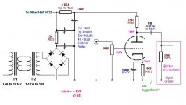
Let's START with something, so here is a 6922/6DJ8 input section.
Needs only a VERY small amount of current 2ma/channel.
100K input impedance should go well with the Sound Card output?
Resistor and cap values in the PS will need to be tailored to whatever transformers/mains voltage you might have.
Let's START with something, so here is a 6922/6DJ8 input section.
Needs only a VERY small amount of current 2ma/channel.
100K input impedance should go well with the Sound Card output?
Resistor and cap values in the PS will need to be tailored to whatever transformers/mains voltage you might have.
Attachments
- Status
- This old topic is closed. If you want to reopen this topic, contact a moderator using the "Report Post" button.
- Home
- Amplifiers
- Chip Amps
- Simple Chip Amp for P to P wiring