The TDA7294 will work with pins 9 and 10 floating or connected to ground. You do not need the resistors and capacitors. The drawback is that you may experience pop noises, when powering the amp up, when you don't use those components.
Pb, I found, if I don't use / floating pin 9 and 10, amp does not sound.
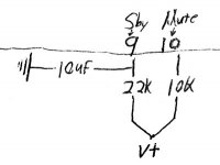
pacificblue, As I learn, If I increase resister & Cap value, It would increase ON/OFF time. Lets take a example for MUTE Pin # 10 default value 10K & 10uf. If I increase the value by 22K & 22uf On/Off time would increase and I would reach the value of ST-BY TIME. If the both Resister & Cap is same then why two resistor & two caps are required ? I would select one Resister attach to PIN # 9 & 10 and another end attach to PIN # 13. (In addition with 22uf cap) What do you think ? Is there any specific reason to keep both Resistor & Caps separate ?
Is there any specific reason to keep both Resistor & Caps separate ?
Mute serves an input function. The mute doesn't require a capacitor; however a 10k resistor is a good idea.
Standby serves an output function. You'll want to have your standby with both resistor and capacitor (for time delay). This capacitor can be 10uF 50v, which are a conveniently small size. The resistor can be 22k.
There is what I believe to be the minimum (3) components.
Edit: If either mute or standby pin happens to break off, you may fuse them together as a repair; however, the amplifier's performance is slightly reduced when mute and standby pins are directly connected together. Its Not recommendable to connect the two directly.
Last edited:
Stand-by is used to waste less energy, when the amplifier is not used during a longer period of time. You would waste even less energy switching the amplifier completely off. The drawback is that cycling the power puts stress on many components. Therefore some people prefer(ed) to waste a little more power in return for longer component life. The stand-by delay avoids popping noises or DC components during the charging time of the power supply. Popping may only be annoying or can destroy tweeters. DC components can become visible, when the woofer cone moves away from its center position and remains there, and can even destroy woofers. That is, why the stand-by had better be delayed.
Mute is used to switch the amplifier off for a short period of time, e. g. when you have to answer the phone. If you switch the amplifier off or to stand-by during that time, it will cool off. Some amplifiers, when heating up pass through a period of worsened sonic performance until all components have reached their thermal equilibrium. To avoid that, you mute the amplifier.
You can switch both inputs at the same time, if you have no need for the mute function. Negative sonic effects are not likely. The datasheet shows on page 9 how to make a start-up sequence with a single signal designed for a signal level of 5 V. You can use the positive rail-voltage directly, which will reduce the start-up time, so you may have to increase the resistor values accordingly.
check this layout
hii
i have made this layout, most part may be in haste, but i dont have the patiance to make it more ashetical,
i m puting a top view in colour with a component silk screen,
guys replay to this asap please,
i plan to toner transfer the pcb tomor.
the feed back resistor which is behind th chip is actualy below the board on the solder side,
and i have used diode parrallel to resistor for standby section which is coming next to the filter caps,
thanks
with regards
aditya
Attachments
Double check the polarity orientation of the 2 big power caps. V- = pin15
The Mute appears to be hooked up to nothing; however, your board is workable because one could omit that cap and quite easily install a 10k resistor from V+ to pin 10 with the pads already provided by the board. That resistor would either be an 1/8w or a 1/4w that would "stand up." But its workable.
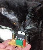
I kind of like your board--its much easier to solder than these:
The Mute appears to be hooked up to nothing; however, your board is workable because one could omit that cap and quite easily install a 10k resistor from V+ to pin 10 with the pads already provided by the board. That resistor would either be an 1/8w or a 1/4w that would "stand up." But its workable.
I kind of like your board--its much easier to solder than these:
Attachments
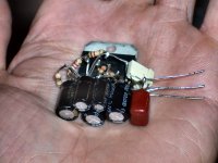
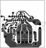
The circuit you have repaired for Pin 9 (standby) looks like the datasheet and that will work really well.
The circuit you have for Pin 10 (mute) looks really bizarre. It doesn't need three resistors. Charge up both the cap and pin 10 with just one resistor to V+.
However, if you would like to save space, Pin 10 doesn't require a capacitor. It does require the resistor Example: Pin 10 with a single 10k resistor to V+.
I don't like it that the board may interfere with and/or block some of the heatsink. Most TDA7294 boards do this, but its still an unfortunate thing to do. Perhaps try to avoid laying circuit traces rearwards of the amp chip?
EDIT: The 47uF (or 22uF) bootstrap cap need to be a bit farther away from the heatsink so that the cap doesn't overheat and leak.
That's all I can think up right now.")
The circuit you have for Pin 10 (mute) looks really bizarre. It doesn't need three resistors. Charge up both the cap and pin 10 with just one resistor to V+.
However, if you would like to save space, Pin 10 doesn't require a capacitor. It does require the resistor Example: Pin 10 with a single 10k resistor to V+.
I don't like it that the board may interfere with and/or block some of the heatsink. Most TDA7294 boards do this, but its still an unfortunate thing to do. Perhaps try to avoid laying circuit traces rearwards of the amp chip?
EDIT: The 47uF (or 22uF) bootstrap cap need to be a bit farther away from the heatsink so that the cap doesn't overheat and leak.
That's all I can think up right now.
Last edited:
hii
thank you for the reply
1) the feed back resistor is on the bottom , and heat sink i m using is (P4 old one) and its cooled with a fan,
2) even i dont like to drag tracks on the back of the chip, but thats the only way to reduce the feedbck path , ( LM1875 would work well wiht a smd register without coming in path of any tracks pin 2 and 4 )
3)47Uf is quiter away from the heat sink i have checked it, and i ahave used a bigger foot print fro it,
4) my man concern is i probably wont get enough power as i due to some financial issue had to satifisy wiht a 34 CT /5 amps and my speakers are 8ohms
so i dont know how much out put i would get , datasheet shows some thing like 35 watts max,
and my speakers are 45watts continus powr - dayton dc130 classic woofer and hivi tweeter 30 watts 8ohms
need to make a speaker box thats going to be a big thign for me.
my TDA7439 firmware is ready so not issue with that luckly
. . . My main concern is I probably won't get enough power as i due to some financial issue had to satisfy with a 34 CT /5 amps, and my speakers are 8 ohms, so I don't know how much output I would get; datasheet shows some thing like 35 watts max, and my speakers are 45watts continus powr - dayton dc130 classic woofer and hivi tweeter 30 watts 8ohms; need to make a speaker box thats going to be a big thing for me. . .
DC130? The 5-1/4 woofers? Power? Um? Double-Voight, also called Half-wave box? That's two quarter wave boxes, one feeding the other, one behind the other (inverted) with the horn output at top. Its colloquially termed "ceiling cannon" and yes that is a lovely challenge, but then you can use DC130 and "power" in the same sentence.
Is this a pop quiz? 34ct transformer, which is 17-0-17 vac, right? Then its 25-0-25 DC at the output of your power supply board.
It is fine for those woofers with TDA7294.
If you gave DC130 more power, it would x-max with a sort of loud "pop" sound. The DC130 are quite durable and could withstand a lot of that, although its not musical with frequent x-max noises.
SO, if you want to push DC130 to x-max with TDA7294 and your 34vct transformer. . . bridge the TDA7294--its really easy with your board. To do it, you connect a resistor between the NFB cap and the Bootstrap cap--see the datasheet for more details.
p.s.
Personally, I would like to see available space to use 2 of 100uF cap per each rail (makes 200uF). And, this is because its difficult to find (and near impossible to source) signal grade hi-fi caps in sizes larger than 100uF. ST doesn't make the cleanest amps, but they can get really clean if given a Lot of extra effort with the power supply. EDIT: and if the power is really clean, then your heatsink will work just fine without the fan.
Last edited:
actually i jsut saw the datasheet again , i think i have done the 9 & 10 pin correctly , 10 is mute with diode parrallel to resistor and this is in series with 10k , to vcc
and 9 is capacitor pulled up . m i wrong in interpreting some where
please let me know
The board will work fine.
However, both mute and standby can use simple "capacitor pulled up" which is simpler.
For "simplest" you can omit the capacitor from the mute; however, its just fine if the board has a spot to install that capacitor. So, the "places to put extraneous parts" is not a problem.
hii
u mean to say that if i have 100 uf or 330 uf instead of the 2200 nichicon , per rail it would nice, or i need to keep both of them , i didnt really get that point,
Well, here it is: The TDA7294 "can" react badly with extra heat and muddy sound if there are any caps larger than 330uF at the amplifier board. SO, put the big caps on the power supply board.
Check out the discrete amplifiers in the solid state forum because the majority do the exact same thing. P.S.
My personal preference would have room to put 2 of 100uF for the v- rail. . . and 2 of 100uF for the v+ rail. . . and a single 2uF (polyester tweeter cap) from v+ to v- at the amplifier board. This is quite clear sound.
- Status
- This old topic is closed. If you want to reopen this topic, contact a moderator using the "Report Post" button.
- Home
- Amplifiers
- Chip Amps
- help in building TDA7294