Assuming you measure the voltage across the Re without signal, then your measurement shows underbiasing. Vbe < 0.6V so no bias current so no drop across Re. Increase the bias until you see Vre rising, until you have the desired bias current.
jd
Janneman,
Thanks for the help. I ended up rebuilding it completely and am now getting bais, this time too much (0.93v emitter to emitter), but, have worked out with the simulation what my resistor values should be. I will try the new resistor values this evening. I'm trying to implement Bob Cordell's Thermal Trak bais scheme.
Ken
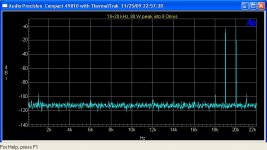
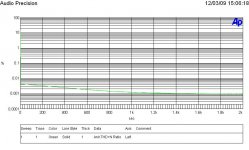
IMD is said to be more important for indicating sonic performance. Here is an FFT of 19+20 kHz at 80 W peak into 8 Ohms of the Compact 49810 with ThermalTrak. The corresponding IMD is 0.001 %.
Very good!
JD
Hello panson,
Have you considered to use some kind of different compensation, eg. like Edmond Stuart TMC? It can bring down some harmonics generated in OPS by a few decibels. Do you have time to test it?
Here are some details about it:
http://www.diyaudio.com/forums/soli...e-feedback-13.html?postid=1160022#post1160022
http://www.diyaudio.com/forums/soli...e-feedback-13.html?postid=1160424#post1160424
http://www.diyaudio.com/forums/soli...e-feedback-14.html?postid=1160590#post1160590
Cheers
Hello panson,
Have you considered to use some kind of different compensation, eg. like Edmond Stuart TMC? It can bring down some harmonics generated in OPS by a few decibels. Do you have time to test it?
Here are some details about it:
http://www.diyaudio.com/forums/soli...e-feedback-13.html?postid=1160022#post1160022
http://www.diyaudio.com/forums/soli...e-feedback-13.html?postid=1160424#post1160424
http://www.diyaudio.com/forums/soli...e-feedback-14.html?postid=1160590#post1160590
Cheers
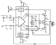
I meant something like this:
The value of Cc would be as in original design, Cc2 should be 5 to 10 times Cc, and Rc is determined from R=1/(2*pi*f*(Cc+Cc2)) where f is the frequency when the circuit slowly reverts to a conventional and safe scheme.
I have drawn two ways to apply this compensation. The first way (1 in schematic) is more conservative and includes VAS only, where the second way gives less THD, because it includes the predrivers also, but can have more problems with local stability.
Attachments
Hello panson,
Have you considered to use some kind of different compensation, eg. like Edmond Stuart TMC? It can bring down some harmonics generated in OPS by a few decibels. Do you have time to test it?
Cheers
Hi blueskyins,
I love to try these compensations in order to learn more. Let me read the threads to get ready. Thanks!
Panson
Hi blueskyins,
I love to try these compensations in order to learn more. Let me read the threads to get ready. Thanks!
Panson
OK, I'm looking forward to this. My LME's will arrive in a month or two and I will definitively try this compensation. Unfortunately, I don't have precise instrumentation as you to measure the benefits if any.
Cheers
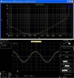
THD vs time from cold start
Output at 18 W into 8 ohm. THD vs time from a cold start. It takes about 20 min to reach the min. THD level (optimum set point).
Bias scheme: Two ThermalTrak diodes in series with a 1 k pot.
Output at 18 W into 8 ohm. THD vs time from a cold start. It takes about 20 min to reach the min. THD level (optimum set point).
Bias scheme: Two ThermalTrak diodes in series with a 1 k pot.
Attachments
Output at 18 W into 8 ohm. THD vs time from a cold start. It takes about 20 min to reach the min. THD level (optimum set point).
Bias scheme: Two ThermalTrak diodes in series with a 1 k pot.
Hello Panson_hk
Why dont you plot 20-20Khz THD curve into 8R with 80Khz bandwidth and 18W and 80Watts.
Regards
Arthur
Hello Panson_hk
Why dont you plot 20-20Khz THD curve into 8R with 80Khz bandwidth and 18W and 80Watts.
Regards
Arthur
Please visit my web site for such curves.
Hello Panson,
about possible compensation optimization. Have you tried it?
I have not tried other compensation yet since I am doing bias tracking improvement for ThremalTrak.
When using a driver like mje15030/31, in my case pushing 3 set of irfp240/9240, is there a rough calculation of how much the drivers should be biased to? Or is it an adjustment by monitoring a scope ? With 53volt rails, and 400 ohms strung from 15030 emitter to the 15031 emitter get 7.39 volts for about 18mA. Seems that voltage is fixed based on how much biasing the output stage, ~150-200mA I am using. Then the bias current through the driver just manipulated with that resistor since the 7.39 for me seems fixed based on that power stage bias choosing.
Just wondering if there is a rule of thumb...
Just wondering if there is a rule of thumb...
When using a driver like mje15030/31, in my case pushing 3 set of irfp240/9240, is there a rough calculation of how much the drivers should be biased to? Or is it an adjustment by monitoring a scope ? With 53volt rails, and 400 ohms strung from 15030 emitter to the 15031 emitter get 7.39 volts for about 18mA. Seems that voltage is fixed based on how much biasing the output stage, ~150-200mA I am using. Then the bias current through the driver just manipulated with that resistor since the 7.39 for me seems fixed based on that power stage bias choosing.
Just wondering if there is a rule of thumb...
Hi traw,
We shall bias driver in class-a, i.e. the current never stops. Since you are using MOSFET output, you don't need to worry about the current value for class-a operation. The driver is always in class-a mode.
The simulation confirms that gate current is so little to pull driver output of class-a mode.
On the other hand, we need some calculation for BJT output.
Attachments
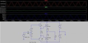
I guess the thing i wonder is how much current should I run through the driver? Your sim seems to show 45mA. I am currently using about 18mA with 400ohm R4. I started with 200ohm R4 and was at 36mA and mje1503X devices were getting quite warm (have slip on to220 heatsinks on them). Not sure if should drop down to even lower mA by increasing R4 or need to have more current running through - ideally little as needed to do the job and most performant of course. thanks
I do like the sound using driver with the IR mosfets better than driving straight off lme, using lme49830 though.
I do like the sound using driver with the IR mosfets better than driving straight off lme, using lme49830 though.
I guess the thing i wonder is how much current should I run through the driver? Your sim seems to show 45mA. I am currently using about 18mA with 400ohm R4.
45 mA in the sim is just an arbitrary value. The main point is that the current is practically constant. You can set it according to sonic performance and heatsink requirement.
You compared sonic performance between 49830 and 49810+driver?
You compared sonic performance between 49830 and 49810+driver?
It was sonic impression of 49830 running 4 fets directly versus running 6 fets with a driver, liking the latter better.
Ah ok... I thought maybe there was some rule of thumb could use to choose right ballpark of current, guess experiment away. Need to get scope.
Have not tried 49810. Boards I have made for 30, though tried once to tweak for some sample 49810 with failure and just shelved the experiment - not sure what missed as thought diff was just need to feed another pin with 5volts or something like that.
- Home
- Amplifiers
- Chip Amps
- Compact Sized LME49810/11 +ThermalTrak Amp