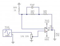
It's just a simple schematic to show the bass boost.
If the source is DC coupled you don't need the cap at the input of your gainclone.
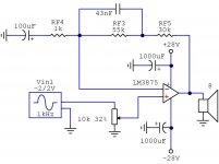
I have attached the real schematic of my ''bass boost'' GC.
My other GC has no bass boost, no input cap, no RF attenuation, no zobel filter at the output and no DC block on the NFB loop. It only has local decoupling 1000uF caps on power pins. It's just like all the other stripped versions of the GC on the net. It has max 35mV of DC at the output and I can hardly believe this will kill my loudspeakers.
Input cap and the cap on negative input to ground have big impact on sound and once I've removed them I'm not going back.
Just try it and see. But first measure DC offset at the output before you connect the loudspeakers.
Regards
If the source is DC coupled you don't need the cap at the input of your gainclone.
I have attached the real schematic of my ''bass boost'' GC.
My other GC has no bass boost, no input cap, no RF attenuation, no zobel filter at the output and no DC block on the NFB loop. It only has local decoupling 1000uF caps on power pins. It's just like all the other stripped versions of the GC on the net. It has max 35mV of DC at the output and I can hardly believe this will kill my loudspeakers.
Input cap and the cap on negative input to ground have big impact on sound and once I've removed them I'm not going back.
Just try it and see. But first measure DC offset at the output before you connect the loudspeakers.
Regards
Attachments
It only has local decoupling 1000uF caps on power pins
I believe in adding 100nf additional.
Input cap and the cap on negative input to ground have big impact on sound and once I've removed them I'm not going back.
Yet, I can use good quality cap for no risk.
")
We are still talking about the TDA2050, right? The datasheet absolute max supply voltage is 50 volts or +/-25v. These small ICs need to get rid of a bunch of heat from the TO-220 package. I wouldn't push them beyond +/- 18 volt with 4 Ohm loads or +/-23 volts with 8 Ohm loads. They should be bolted directly to a heatsink of sufficient size with 5mm or more backplane.
We are still talking about the TDA2050, right? The datasheet absolute max supply voltage is 50 volts or +/-25v.
sorry i was talking abt the 3875 IC which i saw in the bass boost schematic. For TDA2050, 15-0-15 or 18-0-18 transformer will be good.
As a matter of fact, i myself is having TDA2050 amp to assemble. i had finished the layout on a general purpose PCB, but still to do connections. Not finding time for that.
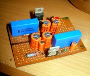
Circuit is same as available in datasheet. picture is shown in attachment.
layout is simple, left side is signal input & feedback, center contains power supply caps and right side is output with zobal network. Simple.
Circuit is same as available in datasheet. picture is shown in attachment.
layout is simple, left side is signal input & feedback, center contains power supply caps and right side is output with zobal network. Simple.
Attachments
Last year I had build TDA2050 as per Rod Elliott's Project # 72, it was good sounding amp.
Ya, TDA2050 is a good chip and TDA7294 sialso very good for higher power. And best part is that these are easily and cheaply available in India.
Normally i have seen that DIYaudio is little more biased for LM series chips.
Normally i have seen that DIYaudio is little more biased for LM series chips.
TDA series is cheap and easily available in my city. At my start-up stage, I played lot-off TDA series TDA2030,TDA2050,TDA7265,TDA7294 etc. Now I am playing LM series, its a matter of test which one is sounding best. LM1876 is good sounding chip for me. But I could not live long with it, because of low power.
In my city I have seen most of the cheap audio systems uses TDA2030 some of 5.1 system sounds really good. I always wanted to know how they produce such a bass from TDA2030 bridge, as well as treble also not bad.
- Status
- This old topic is closed. If you want to reopen this topic, contact a moderator using the "Report Post" button.
- Home
- Amplifiers
- Chip Amps
- Require advise on tda2050 this schematic