I WILL TRY ANOTHER WAY TO CONFIGURE LM3886.
THE LM3886 DATASHEET only recommend how to configure lm3886 in no-inverting & inverting mode that is voltage feedback.i wonder why nsc have not suggestion current mode.
anyway,the sch file attached.i will try it weekend i hope great.
ZANG
THE LM3886 DATASHEET only recommend how to configure lm3886 in no-inverting & inverting mode that is voltage feedback.i wonder why nsc have not suggestion current mode.
anyway,the sch file attached.i will try it weekend i hope great.
ZANG
Attachments
yes,my bookshelf is 4ohm.
by the way,the R4 can be ignored.it is going to extremity simple.
Your bookshelf is nominally 4 ohms. This value will vary wildly over the audio band, perhaps from 2 ohms to 20 ohms. That means your gain, and thus your final frequency response, will also vary wildly over the audio band. I guess you don't want that?
In most designs with this kind of current drive the speaker is a wideband driver without xover that has a relatively flat impedance response, or with more complex speakers some kind of impedance or other equalisation is used.
jd
This type of hookup can be a hell to get stable, with an amp like the LM3886 which needs noise gain > 20dB.
For example any capacitance of the speaker wire would pose a problem here, or a shorted speaker wire
Normally full current-type output (not current-feedback, but we have discussed this naming conventions before") ) is not really needed, a high enough Zout is sufficient and more stable to implement, see ESP project 56, mixed-mode feedback:
) is not really needed, a high enough Zout is sufficient and more stable to implement, see ESP project 56, mixed-mode feedback:
http://sound.westhost.com/project56.htm
Still it would need some compensation for the LM3886 to remain stable under all conditions.
If true current output is wanted, there are better circuits which are *not* based on schemes where the load alters the operating conditions for the opamp.
- Klaus
For example any capacitance of the speaker wire would pose a problem here, or a shorted speaker wire
Normally full current-type output (not current-feedback, but we have discussed this naming conventions before
) is not really needed, a high enough Zout is sufficient and more stable to implement, see ESP project 56, mixed-mode feedback:http://sound.westhost.com/project56.htm
Still it would need some compensation for the LM3886 to remain stable under all conditions.
If true current output is wanted, there are better circuits which are *not* based on schemes where the load alters the operating conditions for the opamp.
- Klaus
I've been experimenting with the circuit below. The pot makes the output impedance adjustable. Thus far it seems to work OK. No oscillations visible on the scope. Measuring speaker distortion, it's kind of cool to adjust the output impedance knob and watch distortion go down as you bias it toward a current source. I have one built, I'll be making an active 3-way, so only 3 more to go (2 LM3886 for the woofers, 2 LM4780 for the mid/tweet)
(2 LM3886 for the woofers, 2 LM4780 for the mid/tweet)Attachments
I'm glad I found this and no need to start a new thread - after all LM3886 threads are already too many....
The diagram in the 1st post look strange to me. Don't know how it turned out since there's no update over a year.
I try mixed mode (both voltage and current) feedback on this chip and it works That's according to the ESP site (mentioned above in #6 post by KSTR).
As I brought up in another thread, I need about 20 Ohm output impedance to make the system Q= 1.1 to my OB bass (with a woofer of 0.29 Qts).
So, my setup is:
Rf1 = 91k
Ri = 1k
Ci = 220uF
(look figure 1 of the datasheet for their positions)
and Rsense = 0.22 R (in series with the load, to pickup current signal)
I built this prototype with a mindset of building a (breadboarded) tube amp which I'm more familiar with. I use unregulated PSU with good old CLC filter which is seldom seen in the world of chip amps.
The power trafo I have on hand is 28V output, so it's approaching the limit of the chip. I got +/- 41.5V after the filter, just +/- 0.5V shy of the line. The load is a woofer for under 240Hz, the measured impedacnce is ranging from 8.2 Ohm to 200 Ohm (fs peak), so I guess I'm OK with that voltage.
There're so many beautifully and tidily made chip amps around here, just can not do that, I'm almost too embarrassed to post the pics of mine. Ah~ what the heck, never mind, here it is.
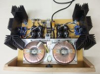
Topless MDF chassis with plywood front panel:
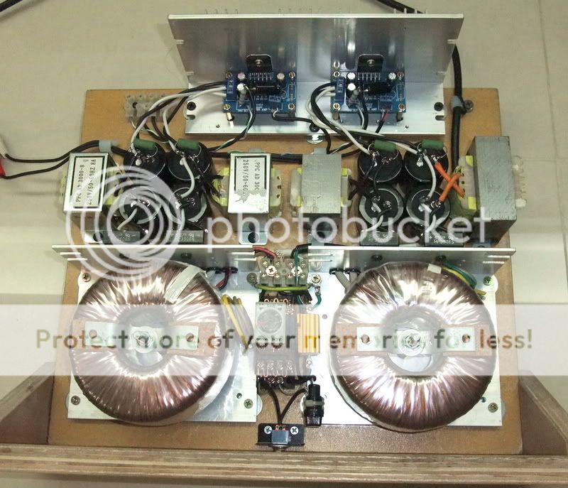
Overkill power supply - my style Unmatched power filter chokes because those are what I have. With very little DCR, they don't affect the rail balance, at least at idle. Perfect +/- 41.5V on both channel
The chips run hotter than I expected, so I added some more heatsinks on the back:
However they help very little. The temperature is about high 40s degree C. Very warm to touch, obviously higher than body temperature but OK to touch it continously. Eventually I added a small fan to cool it down to my like. I think wood chassis is very much inferior to metal in loosing heat. (my other tube amp suffers from this, too)
The boards (bought from local web auction seller).
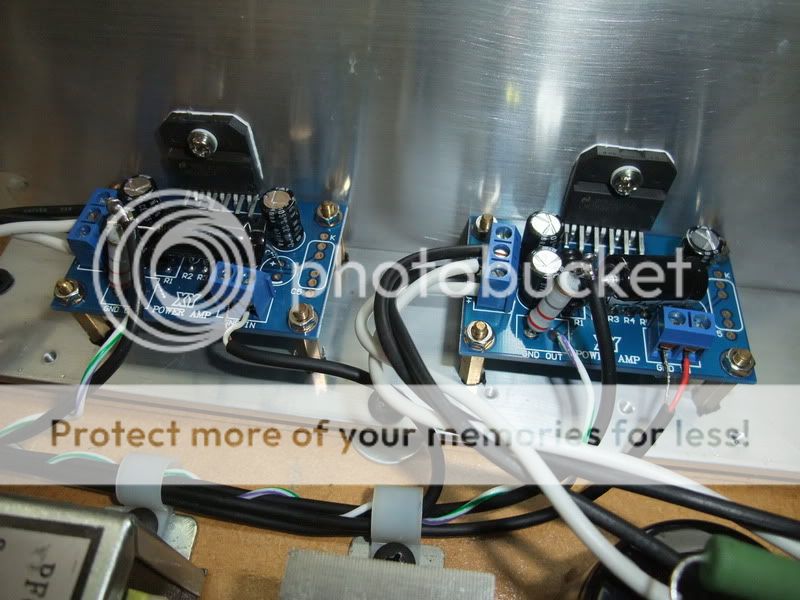
You may see the 'add-on' parts -- standing but tilted 2W resistor is the Rsense, and the 'floating' cap is the Ci.
Overall a messy mockup but it worked fine in the first 2 hours test (and the bass performance is very good). No audible hum or noise, turn on and off quietly. 9mV output offset. (all these are much better than my old Hafler)
Look much nicer if step back a little
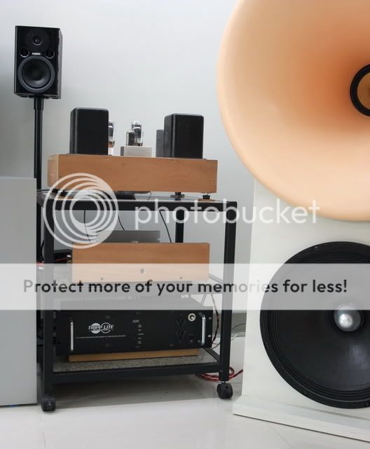
(The middle one in the rack)
The diagram in the 1st post look strange to me. Don't know how it turned out since there's no update over a year.
I try mixed mode (both voltage and current) feedback on this chip and it works
That's according to the ESP site (mentioned above in #6 post by KSTR). As I brought up in another thread, I need about 20 Ohm output impedance to make the system Q= 1.1 to my OB bass (with a woofer of 0.29 Qts).
So, my setup is:
Rf1 = 91k
Ri = 1k
Ci = 220uF
(look figure 1 of the datasheet for their positions)
and Rsense = 0.22 R (in series with the load, to pickup current signal)
I built this prototype with a mindset of building a (breadboarded) tube amp which I'm more familiar with. I use unregulated PSU with good old CLC filter which is seldom seen in the world of chip amps.
The power trafo I have on hand is 28V output, so it's approaching the limit of the chip. I got +/- 41.5V after the filter, just +/- 0.5V shy of the line. The load is a woofer for under 240Hz, the measured impedacnce is ranging from 8.2 Ohm to 200 Ohm (fs peak), so I guess I'm OK with that voltage.
There're so many beautifully and tidily made chip amps around here, just can not do that, I'm almost too embarrassed to post the pics of mine. Ah~ what the heck, never mind, here it is.
Topless MDF chassis with plywood front panel:
Overkill power supply - my style
Unmatched power filter chokes because those are what I have. With very little DCR, they don't affect the rail balance, at least at idle. Perfect +/- 41.5V on both channelThe chips run hotter than I expected, so I added some more heatsinks on the back:
However they help very little. The temperature is about high 40s degree C. Very warm to touch, obviously higher than body temperature but OK to touch it continously. Eventually I added a small fan to cool it down to my like. I think wood chassis is very much inferior to metal in loosing heat. (my other tube amp suffers from this, too)
The boards (bought from local web auction seller).
You may see the 'add-on' parts -- standing but tilted 2W resistor is the Rsense, and the 'floating' cap is the Ci.
Overall a messy mockup but it worked fine in the first 2 hours test (and the bass performance is very good). No audible hum or noise, turn on and off quietly. 9mV output offset. (all these are much better than my old Hafler)
Look much nicer if step back a little
(The middle one in the rack)
Last edited:
The chips look like the LM3886tf (insulated package) Although they are simpler to deal with, the uninsulated package (LM3886T) with a silpad or mica and heatsink grease insulator have better transfer of heat to heatsink. However, speaker seems like an easy load to drive. Somewhere in the future I plan to try some experiments with output impedance. Good luck with it.
Yes, those are ~TF.
Plastic case looks like having higher thermal resistance. And our common sense says so, too. However I don't find any description about it in the datasheet. It just says the thermal resistance is 1 degree C / W, no related package info is mentioned.
My previous set up was indeed very warm, especially I run it near the voltage limit.
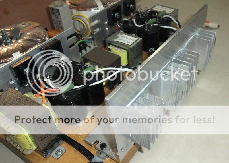
And, since the chokes are out, I made a re-layout with larger heatsinks. Now it's stone cold Nah, not really cold, but very cool indeed.
Plastic case looks like having higher thermal resistance. And our common sense says so, too. However I don't find any description about it in the datasheet. It just says the thermal resistance is 1 degree C / W, no related package info is mentioned.
My previous set up was indeed very warm, especially I run it near the voltage limit.
And, since the chokes are out, I made a re-layout with larger heatsinks. Now it's stone cold
Nah, not really cold, but very cool indeed.Attachments
I checked the data sheets and found the same as you. However, on the application notes http://www.national.com/an/AN/AN-1192.pdf for LM3886 they do show lower power rating at the bottom of page 4. Perhaps mica isolator is equivalent thermal conductivity to isolated package? Sounds like you have it under control anyway.
Thanks for the link, it's good to know. I'll feed it with some pipe organ or bombs in the coming weekend to see if it stands alright.
BTW, an interesting observation about the temperature. It's not uniform throughout the whole heatsink. It's slightly warmer near the chip, cooler towards the outer area. And it's even warmer at the chip itself, not much but detectable.
The surface of the heatsink is reasonably flat, and I did apply a proper thin coat of thermal compound between chip and heatsink. Is there a heatsink that is too big? It seems the heat is 'not enough' to spread to the whole thing and dissipates a lot along the path... (and that almost ridiculous proportion of the physical sizes of that chip and heatsink, not commonly seen in other discrete amps in which the output devices are bigger and spreaded in larger area... )
Another interesting observation is that the temperature reflects the operation of the chip quite obvious and very quick. One night I played that famous [Waltz for Debby _ Bill Evans], and the heatsink on the left was obvious warmer than the other - this amp serves the bass only, and the acoustic bass of this recording is at the far left.
Following that, I played another CD with evenly spreaded bass between channels (I forget which), within minutes, the warmer left cooled down and the cooler right warmed up and they became equal in temperature. It was not loud at all, just conversation level. How interesting. I never had that before.
This chip must be biased very shallow, very near pure class B.
BTW, an interesting observation about the temperature. It's not uniform throughout the whole heatsink. It's slightly warmer near the chip, cooler towards the outer area. And it's even warmer at the chip itself, not much but detectable.
The surface of the heatsink is reasonably flat, and I did apply a proper thin coat of thermal compound between chip and heatsink. Is there a heatsink that is too big?
It seems the heat is 'not enough' to spread to the whole thing and dissipates a lot along the path... (and that almost ridiculous proportion of the physical sizes of that chip and heatsink, not commonly seen in other discrete amps in which the output devices are bigger and spreaded in larger area... )Another interesting observation is that the temperature reflects the operation of the chip quite obvious and very quick. One night I played that famous [Waltz for Debby _ Bill Evans], and the heatsink on the left was obvious warmer than the other - this amp serves the bass only, and the acoustic bass of this recording is at the far left.
Following that, I played another CD with evenly spreaded bass between channels (I forget which), within minutes, the warmer left cooled down and the cooler right warmed up and they became equal in temperature. It was not loud at all, just conversation level. How interesting. I never had that before.
This chip must be biased very shallow, very near pure class B.
the reason the heatsink has a very high temperature drop across it, is because the back plate is too thin.
I can see from the old To3 monting holes that this had 4 devices very close to the sides where the main sink fins would do most of the work.
You are asking the thin back plate to spread the heat too far away from the single device.
I can see from the old To3 monting holes that this had 4 devices very close to the sides where the main sink fins would do most of the work.
You are asking the thin back plate to spread the heat too far away from the single device.
Thanks again, Andrew,
The black plate of the heatsink is 5mm thick, just the same as those on my old Hafler. And such 'problem' in temperature distribution does also happen on Hafler - it's slightly wamer on the rear half where the MOSFETs are mounted. It's more detectable when the ambient temperature is lower.
I guess a thick copper bar across the whole width can help, but maybe it does not really need it. I've not yet tested it for the 'high power operation'. Will update soon.
Hi,ust the same as those on my old Hafler.
your implementation shows one device in the middle near the bottom of the backplate.
I have not seen how Hafler did it!
I think you are not comparing like for like.
The Hafler I mentioned is SE120 (the smallest one I guess). I don't have its photos readily on hand, so...
It's PCB occupies the rear half of the chassis while leaving the front half for power transformer (and a fuse holder and a switch). Their output devices - on both sides of the PCB - are mounted horizontally on L-shape aluminum blocks and then onto the rear half of heatsinks.
It's not the same as my chip amp now, I agree. What I meant is their behavior on the heat distribution on the heatsinks -- not evenly spread on both of them.
Anyway, I gave it a workout yesterday - playing loud bass for some time. Not the loudest or longest at my place, but loud and long enough. It stayed cool, only slightly warmer. Being warmer than 'normal condition', it seems the temperture on heatsink is spreaded more evenly. Interesting. (This also happens on my Hafler, it's evenly warmed up when I bias it higher, or in warmer ambience.)
So, anyway, at least there's nothing to worry about the dissipation of the chips
I've been experimenting with the circuit below. The pot makes the output impedance adjustable. Thus far it seems to work OK. No oscillations visible on the scope. Measuring speaker distortion, it's kind of cool to adjust the output impedance knob and watch distortion go down as you bias it toward a current source. I have one built, I'll be making an active 3-way, so only 3 more to go
This is schematic is right direction.

- Status
- This old topic is closed. If you want to reopen this topic, contact a moderator using the "Report Post" button.
- Home
- Amplifiers
- Chip Amps
- Lm3886 current feedback