I currently have 2 half working power amplifiers that I was wondering if somebody could help me with.
The first is a 500wRMS(2x250w) amplifier which I bought half working over a year ago. At the time the right channel worked fine but the left channel had a broken volume pot. After replacing the pot and cleaning the amplifier it worked fine and has done ever since. Suddenly last week the left channel again stopped working.
The channel will no longer let any signal through it, but there is just a hiss which gets louder as the volume pot is turned up. I have checked the soldering on the board and all appears to be fine there.
I am by no means an expert in amplifier operation or electronics but I am guessing that due to the fact the hiss gets louder as the volume is turned up the problem probably lies before the output stage. Is this correct?
After having read a number of things on the Internet I think the problem could be a dried up capacitor. Is this correct and if so how would I check for this?
Also are there any general things that people could suggest I check? Or that I should check in order to provide more information on the problem?
I will ask about the other amp later so as not to confuse the topic.
Thanks for your time.
Kind Regards
Dave
Warning: You could easily be killed, while working inside of equipment that is connected to the AC mains, and could even be killed if the equipment is not connected to anything.
If you have inspected everything, visually, with a magnifier, and can't see anything suspicious, you can try the following.
Since there are two channels, which should be almost identical but are not, a multimeter or volt-ohm meter might get you to the problem. (But even a cheap or very old oscilloscope would be extremely useful.)
The basic method would be to measure something at corresponding points in the two channels, proceeding from either inputs to outputs or outputs to inputs. When you find a difference, you have probably found a clue to finding the problem.
With the amp powered on, but with no input, for example (and all controls set identically, between channels), you could connect the negative voltmeter lead to the central ground and use the other lead to measure the DC voltages at corresponding points in both channels. With the amp powered off (and all capacitors discharged), you could also try measuring resistances, similarly.
There is often much more to it, of course, unless you get lucky. But it sounds like you probably don't have much test equipment or troubleshooting experience. Also, SAFETY should be a huge concern.
Also, if the amp is relatively old, you could try replacing all of the electrolytic capacitors. But you could start with any that look like they are leaking or bulging. You might also be able to find really-bad ones by measuring across them (AC and DC volts when powered, Ohms when unpowered after all caps discharged), and comparing to measurements of corresponding caps in the working channel.
Good luck.
Hi,
Thanks for your help guys. Will try testing the amp with a multimeter like you suggested and will see if that turns up anything.
The amp is an Avitech Beta 500, its about 25 years old now. Can probably get some pictures of the inside, will dig out my camera tomorrow.
Kind Regards
Dave
Thanks for your help guys. Will try testing the amp with a multimeter like you suggested and will see if that turns up anything.
The amp is an Avitech Beta 500, its about 25 years old now. Can probably get some pictures of the inside, will dig out my camera tomorrow.
Kind Regards
Dave
After having tested the amp with a multi meter it seems to have gotten slightly worse  (I know, I only have myself to blame).
The amp now has no working sides. The right side which was working will only now work at very low volumes. At high volumes it sounds like its clippping terribly. Also for some reason now when you play music through the right hand side the VU meter on the left hand side lights up aswell :S Not entirely sure but I must have shorted something...
There were a few strange things that I found when measuring voltages. Firstly all capacitors seemed to be working on the left hand side (the side that was broken first of all).
Also there was one transistor on the right hand side which had 60V DC between its base and the central ground. Now I'm no expert but that sounds very wrong to me :S But that was the right, working side. There was no corresponding voltage on the left, broken side.
Does anyone have any ideas as to firstly what I might have done to break the amp further and any ideas about how I might fix it. Secondly can anyone shed any light on why there was 60V across the base of a seemingly working transistor when no similar voltage was across the base of the transistor on the broken side.
Thanks for much for your help. Glad to see the place is back up and running
Regards
Ps. My camera has run out of batteries and I don't have the charger. The two pictures I did mange to take of the amp that are on there can't be taken off as I have lost the cable (bad times). Will attempt to get them off at work...
(I know, I only have myself to blame).The amp now has no working sides. The right side which was working will only now work at very low volumes. At high volumes it sounds like its clippping terribly. Also for some reason now when you play music through the right hand side the VU meter on the left hand side lights up aswell :S Not entirely sure but I must have shorted something...
There were a few strange things that I found when measuring voltages. Firstly all capacitors seemed to be working on the left hand side (the side that was broken first of all).
Also there was one transistor on the right hand side which had 60V DC between its base and the central ground. Now I'm no expert but that sounds very wrong to me :S But that was the right, working side. There was no corresponding voltage on the left, broken side.
Does anyone have any ideas as to firstly what I might have done to break the amp further and any ideas about how I might fix it. Secondly can anyone shed any light on why there was 60V across the base of a seemingly working transistor when no similar voltage was across the base of the transistor on the broken side.
Thanks for much for your help. Glad to see the place is back up and running
Regards
Ps. My camera has run out of batteries and I don't have the charger. The two pictures I did mange to take of the amp that are on there can't be taken off as I have lost the cable (bad times). Will attempt to get them off at work...
If you shorted the output then you may have blown (assuming it has them) one or more of the rail fuses. My Amp behaves this way when it has a blown fuse ie will play soft but very distorted if turned up.
On the original problem, my guess woul dbe that you have a problem between the input and the volume pot. I'd be suspicious of any caps in the input path. you could try (using clip leads) bypassing the cap(s) using a new one of similar value, if a cap has gone open circuit, you won't get any signal through it to your volume pot.
If you can find a circuit for a signal injector, (something that creates a low level sine wave or similar) you can try probing various places along the input path to try and determine where the problem is. Of course you need to be careful doing this not to short anything!
Tony.
I currently have 2 half working power amplifiers that I was wondering if somebody could help me with.
The first is a 500wRMS(2x250w) amplifier which I bought half working over a year ago.
Errm, 250W (I suppose into 8 Ohm) requires significant rail voltages. Let's see, something like 126 Volts p2p (44 V rms). That means the PSU will be providing in excess of +/- 60 V DC. These are very dangerous voltages.
I just wanted to chime in with one thought . . . is that an integrated amp, or a power amp? If its a power amp, with only a volume control, the volume pot is usually the first component in the signal path. Which means that the problem could be before the input. Have you simply swapped the input cables to see if the problem jumps to the other channel?
Just a thought.
Just a thought.
Oh the irony!!!
I just changed the sata cables in my Mythtv box due to problems with DVD playback, fired it up and wondered why I was only getting one channel.. tried a different source and same deal. My amps right channel is exibiting almost exactly the same symptoms as yours... noting but a bit of hum comming from the midrange and some his from the tweeter. Doesn't seem to vary though with volume control position. Looks like I'm going to be doing my own troubleshooting!
Oh well it gives me an excuse to swap in the gainclone and finally do some real listening on it. Just need to get my mythtv box to play cd's! Doesn't sound too bad at the moment listening to some Paul Kelly playing on ABC digital TV.
edit: mine is a 100W/channel mosfet amp. Did a complete cap changeout about 4-5 years ago, but the amp itself is now over 20 years old.
Tony.
Well thankfully mine was a simple repair didn't even need any test gear... My 20 month old daughter had decided that the hole where the balance pot used to be was just the right size to poke chopsticks through. in the process she managed to jag the rather dodgy connection between a resistor and the main input capacitor to the power amp. Dodgy mod I did ages ago to bypass the tone controls of the amp. Resoldered and back up and running.
Two interesting things came out of this though. First was I got to finally seriously listen to my gainclone (I originally only built if for speaker testing duties). It is surprisingly good, and not at all underpowered. Perfectly fine for my normal listening levels. Bass was good despite the small caps in the power supply, and due to the earth loop breaker installed in it, it doesn't have the hideous hum that my main amp does when hooked up to the htpc. I'm not set up to do A/B comparisons, and it wasn't fair as the GC was being fed direct with no preamp, and the Playmaster was going through the integrated pre, but I suspect that the Gainclone had the better of the bigger mosfet amp in the clarity stakes.
The other interesting discovery was that I had modified the right channel of the amp mosfet, probably after a particular thread in the solid state forum where I asked for suggestions for improvement. I think after the mods (which I did at the same time as a complete recapping, and transistor matching excercise) I had some problems (solder bridge) and gave up and left it as is once working, but I had completely forgotten about it. So the right channel is missing 2 diodes, a resistor and a transistor and has a single resistor in their place... I suspect I was going to do some tests but never did due to the frustration the other problem caused.
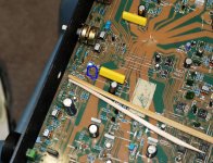
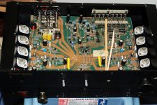
anyway here are a couple of pics of my daughters handywork The circled bit is where the break is. Just shows that it is not always something you would think!!!!
edit: oh and I gaffer taped up the hole, hopefully enough to stop her again. Luckily for me (and her) it was a chopstick and not a screwdriver!
Tony.
Two interesting things came out of this though. First was I got to finally seriously listen to my gainclone (I originally only built if for speaker testing duties). It is surprisingly good, and not at all underpowered. Perfectly fine for my normal listening levels. Bass was good despite the small caps in the power supply, and due to the earth loop breaker installed in it, it doesn't have the hideous hum that my main amp does when hooked up to the htpc. I'm not set up to do A/B comparisons, and it wasn't fair as the GC was being fed direct with no preamp, and the Playmaster was going through the integrated pre, but I suspect that the Gainclone had the better of the bigger mosfet amp in the clarity stakes.
The other interesting discovery was that I had modified the right channel of the amp mosfet, probably after a particular thread in the solid state forum where I asked for suggestions for improvement. I think after the mods (which I did at the same time as a complete recapping, and transistor matching excercise) I had some problems (solder bridge) and gave up and left it as is once working, but I had completely forgotten about it. So the right channel is missing 2 diodes, a resistor and a transistor and has a single resistor in their place... I suspect I was going to do some tests but never did due to the frustration the other problem caused.
anyway here are a couple of pics of my daughters handywork
The circled bit is where the break is. Just shows that it is not always something you would think!!!!edit: oh and I gaffer taped up the hole, hopefully enough to stop her again. Luckily for me (and her) it was a chopstick and not a screwdriver!
Tony.
Attachments
Last edited:
Hi Jacco, yes that is the one I think as a kit it originally sold for $499 AUS. But I got mine on runout for I think $399... that had all generic caps and 5% carbon film resistors... It's had a few mods over the years The one mod I never got around to doing (did do a prototype which worked for one input) was to replace all the cmos switches and buffers with a bank of high quality gold plated relays in the preamp section I was going to arange it so that with no power on any of them CD input was selected. It is probably going to be the main amp for my stereo subs and the Gainclone will take over main duty driving my MTM's when I get them finished and build a new pre/buffer and an active crossover... could be a while! In the mean time I'm going to build an earth loop breaker for it, I hadn't realised how bad the hum was until I plugged in the gainclone
Tony.
I think as a kit it originally sold for $499 AUS. But I got mine on runout for I think $399... that had all generic caps and 5% carbon film resistors... It's had a few mods over the years The one mod I never got around to doing (did do a prototype which worked for one input) was to replace all the cmos switches and buffers with a bank of high quality gold plated relays in the preamp section I was going to arange it so that with no power on any of them CD input was selected. It is probably going to be the main amp for my stereo subs and the Gainclone will take over main duty driving my MTM's when I get them finished and build a new pre/buffer and an active crossover... could be a while! In the mean time I'm going to build an earth loop breaker for it, I hadn't realised how bad the hum was until I plugged in the gainclone Tony.
- Status
- This old topic is closed. If you want to reopen this topic, contact a moderator using the "Report Post" button.
- Home
- Amplifiers
- Chip Amps
- Amplifier Repair