I'm new to building amps so I hope some one can help. I'm building a LM3886 kit from chipamp.com and am getting 2mvdc from the psu. I thought it should be about 30vdc. I've rechecked the entire pcb and can't find the problem. Are there any suggestions. chipamp does not respond to my emails.
Thanks Mike
Thanks Mike
Thanks for the replies,
The transormer is wired correctly and there is the proper acv. when testing from v+ to v- there is the same acv. Is this the way it should be? I thought it should be dcv. I'll build a light bulb tester this weekend. I've been going over this psu for a week, even disassemled it and resolderd everything. Attached is a picture of the psu from chipamp.com. Mine looks the same.
Thanks Mike
Attachments
does the kit have two or one bridge rectifiers?
if one, than the secondaries hook up to that at ~ and ~ pins on the rect. the dcv is output at + and - pins of the rect. your center tap than goes to ground.
if two, than your transformer must have dual secondaries, thus each one (pair of wires) would connect to one of the rectifiers.
!!!!! if your + and - pins have acv on them, this means so do the capacitors, and they soon could explode on you.
if you could draw an mspaint diagram up real quick, showing how you connected transformer wires to the pcb.
edit i see it has diodes. still, we cannot tell what is going on until we can see how it is connected.
Thanks again,
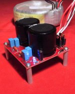
there are two rectifiers. the pcb is clearly marked for the ac inputs, binding posts are soldered there as per instructions. the transformer has two pairs of secondaries. I have never used ms paint so attached is a jpeg of the boards. it is pretty straitforward as to where everything goes and polarity. The bands on the pcb for the diodes indicate metal side.
there are two rectifiers. the pcb is clearly marked for the ac inputs, binding posts are soldered there as per instructions. the transformer has two pairs of secondaries. I have never used ms paint so attached is a jpeg of the boards. it is pretty straitforward as to where everything goes and polarity. The bands on the pcb for the diodes indicate metal side.
Attachments
Hi Mike,
Can you please clarify - you say the PSU output is 2mV DC in the first post, but then that it's the same AC out across + & - as the AC input, in post #5. What is the actual output?
It'd be highly unusual for AC to get past the rectifiers if they are correctly aligned and properly functional, and as you state, it's almost foolproof on these boards because of the band markings, if the diodes are those supplied by Chipamp (MUR860?). If not, make sure the pin polarity is correct (I'm not sure if all diodes in this package are pin compatible - maybe they are?).
BTW I've built one of these kits and it's a nice, compact, good sounding unit when up and operating.
Stuey
Hello again,
Sorry I missed yesterday's posts. I had to get some work done out in the woods. We had some cool weather and had to work on fire protection. Anyway back to the thread. Pulled of the caps, there is both very low dcv and about 26vac. I just checked the diodes again, and am getting low voltage both ways. .945v pos. lead to anode, and .415 neg. lead to anode. This is probably the problem. I will make a light bulb tester before I move on.
Thanks Mike
and here again he plugs in some known faulty equipment and continues to take measurements.mike dodd said:Hello again,
Sorry I missed yesterday's posts. I had to get some work done out in the woods. We had some cool weather and had to work on fire protection. Anyway back to the thread. Pulled of the caps, there is both very low dcv and about 26vac. I just checked the diodes again, and am getting low voltage both ways. .945v pos. lead to anode, and .415 neg. lead to anode. This is probably the problem. I will make a light bulb tester before I move on.
Thanks Mike
Ask for help and ignore the advice you are given.
Is this the way to get further help?
Howdy Mike,
I can't quite make out where you're measuring, but if that's what's on the rails before the caps but after the diodes, it sounds like the diodes are knackered. Is there a possibility you overheated them when soldering?
From memory, though, these boards don't suck out much heat so you shouldn't have needed to use too much to get solder flowing. This is mainly a problem when you're soldering to a board with a fairly big copper trace, or a plane of copper. This pulls the heat out of a smaller tip.
Photos of your work showing the transformer wiring and both sides of the PSU board would may help. You'd be surprised what people on here can spot!
Stuey
- Status
- This old topic is closed. If you want to reopen this topic, contact a moderator using the "Report Post" button.
- Home
- Amplifiers
- Chip Amps
- dc volts