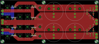
I decided to design a higher current (15A max) unregulated power supply for my BR100 amp. If enough people are interested, I'll do a group buy. The cost will depend on the number of boards ordered, but the most the boards will cost is $30 each (they're big at 7.85" x 3.45").
The diodes can be MUR1520 or any TO-220 diode with the same pin configuration. The reservoir capacitors can be 2-pin or 4-pin snap in with 10mm or 22.5mm lead spacing and up to 40mm diameter. There are also positions for 5mm, 7.5mm and 10mm film capacitors and snubbers, as well as bleeder resistors. There are 4 ground connections to make it easy to connect to either a center-tap or dual secondary transformer. I'll be using 2oz copper and the narrowest traces are 254 mils wide.
Suggestions on the design will be entertained as well.
Attachments
Andrew, your answer is simply the tracewidth of the pcb-artwork.
For your pleasure,
http://circuitcalculator.com/wordpress/2006/01/31/pcb-trace-width-calculator/
Have fun, Hannes
For your pleasure,
http://circuitcalculator.com/wordpress/2006/01/31/pcb-trace-width-calculator/
Have fun, Hannes
That is one of the calculators I used. According to one, the width and thickness was acceptable for 10 degrees rise over ambient, and the other for 12 degrees rise over ambient. I also exceeded the minimum recommended gap of 30 mils for a 35V difference.
I'm not sure what the difference between Ipeak and Itransient is. I understand transient, but by peak do you mean DC? If so, then that would be the one.
I'm not sure what the difference between Ipeak and Itransient is. I understand transient, but by peak do you mean DC? If so, then that would be the one.
It sounds like you are in the dark as much as me when trying to define the output current ability of a standard PSU.
Why don't you call it a +-20mF PSU with integrated rectifier and snubber?
What size of components has the PCB allowed for?
BTW,
the two Ground connections at the input end are not required.
The output end goes to the main Audio Ground. There is no other Ground connection to the PCB.
Why don't you call it a +-20mF PSU with integrated rectifier and snubber?
What size of components has the PCB allowed for?
BTW,
the two Ground connections at the input end are not required.
The output end goes to the main Audio Ground. There is no other Ground connection to the PCB.
The component sizes are in the first post. I plan on using 4x 15mF caps in my implementation, but it'll support a lot more than that (+-112mF 35V, or +-78mF 50V with a quick check of what Digikey has).
As for ground, I was thinking one for connection to PE, one for connection to center-tap (if using such a transformer) and two outputs for connection to two amp modules. Would it be better to have the grounds connected at an off-board star?
As for ground, I was thinking one for connection to PE, one for connection to center-tap (if using such a transformer) and two outputs for connection to two amp modules. Would it be better to have the grounds connected at an off-board star?
If you use a centre tapped transformer then connect the centre tap to the output end or between the caps not at the rectifier end.
If you use twin secondaries connect the zero volts at the output end to the main Audio ground.
You do not need the input Ground on the PCB. That simply copies what folk put in schematics, it is not how to wire up the real PSU.
4 * 10000uF = +-20mF
4 * 15000uF = +-30mF
which is quicker to type?
which is more informative?
I see it now, 40mm diameter.
Hi Redshift,
shift the snubbers close to the rectifiers, that's where they belong")
You may also want to rethink the bypasses at all, bypassing (or decoupling) belongs onto the amp-board.
Have fun, Hannes
PS: by the way, maybe you want to think about thermals as well, otherwise be warned that pads in big copper planes are a pain to solder and need terrific temperatures usually.
shift the snubbers close to the rectifiers, that's where they belong
You may also want to rethink the bypasses at all, bypassing (or decoupling) belongs onto the amp-board.
Have fun, Hannes
PS: by the way, maybe you want to think about thermals as well, otherwise be warned that pads in big copper planes are a pain to solder and need terrific temperatures usually.
The bypasses are optional, I'm leaving them in because I plan on testing them and probably using them. As for the snubbers going close to the rectifiers, are you sure you aren't thinking about the other kind of snubbers (that go directly across each diode)?
I'll revisit thermals. I had put them in, but didn't like how small the connecting paths ended up being. I'll see if I can adjust it.
I'll revisit thermals. I had put them in, but didn't like how small the connecting paths ended up being. I'll see if I can adjust it.
In real life those currents will hardly be present for a long time in an audio amplifier except for class A.Redshift187 said:I decided to design a higher current (15A max) unregulated power supply
Nevertheless 15 A should not pass through a PCB. If you really expect that amount of current, the better way to go is capacitors with screw terminals connected to a massive copper or aluminium sheet, busbar or block. That provides a mechanically stable, low impedance connection with good cooling capacity and can serve as the star-point for all ground connections at the same time.
post #9
Must have sneaked in from the famous CarlosFM Snubberized PSU.h_a said:I thought the R,C parts (R1, C11, R2, C12) are snubbers. As these are connected to ground instead of across the diodes, what is their purpose?
h_a:
The snubbers are there to reduce the inductance of the capacitors. Supposedly they don't work very well without the bypass caps included. Typical values are 0.1uF and 1R. Search for CarlosFM snubber and you'll find large amounts of information to sift through
Some people use them, some don't. I use them on my current power supply, and I'll be doing some comparisons when I have time, now that I have a decent scope.
4fun:
The split kind of defeats putting the center-tap in between the capacitors.
Attachments
pacificblue said:Nevertheless 15 A should not pass through a PCB. If you really expect that amount of current, the better way to go is capacitors with screw terminals connected to a massive copper or aluminum sheet, busbar or block. That provides a mechanically stable, low impedance connection with good cooling capacity and can serve as the star-point for all ground connections at the same time.
That's a good suggestion, but in the end the power supply connects to an amp PCB. Hopefully they wouldn't be expected to supply continuous 15A of current, but I took the max current of the diodes I'll be using (MUR1520) and designed around it.
pacificblue said:Must have sneaked in from the famous CarlosFM Snubberized PSU.
Too true
- Status
- This old topic is closed. If you want to reopen this topic, contact a moderator using the "Report Post" button.
- Home
- Amplifiers
- Chip Amps
- Interest Check: 15A Unreg PSU