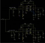
I am designing my own PCB schematic for two LM3886 amplifiers on the same board (stereo). This is what I have made:
I have transformer with two center trapped secondaries that I 'm going to use with this amp.
Can you please check my design for any mistakes? Every advice is welcome before it is to late.
Thank you in advance!
RazoR
An externally hosted image should be here but it was not working when we last tested it.
I have transformer with two center trapped secondaries that I 'm going to use with this amp.
Can you please check my design for any mistakes? Every advice is welcome before it is to late.
Thank you in advance!
RazoR
I don't understand the 1 ohm resistor after the rectification . Is it the correct value ?
Some may use it after the first smoothing capacitor but followed by another with the same value . I would keep the power rails symmetric and shorter , in this case you should cut the input traces and do some wiring over the PCB . Then ,each channel has its own star ground ,but you should think it globally , so instead of a star you could have drawn a circle or a square , which is the same for the purpose .
After : you could have it done in half the space you used , since all the "job" is done by the chip...
The rectifier on the drawing looks like a KBU8 or similar. The datasheet specifies a protective resistor of 0,8 Ohm with 5000 µF and 1,6 Ohm with 2500 µF. 1 Ohm with 3300 µF seems to be a good enough approximation.picowallspeaker said:I don't understand the 1 ohm resistor after the rectification . Is it the correct value ?
Nobody in the forum seems to use those resistors and nobody seems to have problems without them. That does not mean they should not be used. Manufacturers usually don't specify those things for fun, because customers hate any unnecessary additional cost and losses.
The alternative would be a high current bridge rectifier, like the KBPC in 35 A version or so. They can deal with big capacitors without protective resistors.
So the resistor is there only for the in rush current at power up , even to prevent a low wattage transformer to melt ?!?
The grounding for me is wrong . It does symbolize what a star ground is (for a channel) , but it looks like a spider web in this case : Don't be afraid , it probably works , sure it will without any problems .Just the concept ,right ?
The grounding for me is wrong . It does symbolize what a star ground is (for a channel) , but it looks like a spider web in this case : Don't be afraid , it probably works , sure it will without any problems .Just the concept ,right ?
No, it is there to protect the rectifier by limiting the charging current to the capacitors.picowallspeaker said:So the resistor is there only for the in rush current at power up , even to prevent a low wattage transformer to melt ?!?
Amazingly I am also making a guitar amp for my son (who already has two guitar amps), using the same chip as the post amp.
Here is my schematic and board layout (I will have to post multiple times). I only do it in the evenings after work so please feel free to shout if you spot errors.
Here is my schematic and board layout (I will have to post multiple times). I only do it in the evenings after work so please feel free to shout if you spot errors.
Attachments
I thought the supply should be able to deliver full power immediately , as cables for speakers should be near zero resistance . maybe it is not the case for LM38xx series ,as they don't exhibit superb slew rates ;if people can detect difference in cables (transmission) , surely 1 ohm at the generator could cause fatigue at power peaks.
It is ok to over dimension the power of the rectifiers and of capacitors in the supply
BTW I don't understand the huge transformers often used for chip amps.Are they pretended to be used lately in case of chip failure for a discrete design?!?!?!
It is ok to over dimension the power of the rectifiers and of capacitors in the supply
BTW I don't understand the huge transformers often used for chip amps.Are they pretended to be used lately in case of chip failure for a discrete design?!?!?!
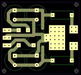
To explain my design (which has not been tested yet), the PSU has space for two large caps on each side of the rails, eg 2 x 4700uF for a total of 9,400uF per rail. I have then attached a fuse holder on each rail just in case. The pool of pads is to mound Japan Solderless Terminals (JST), 4.8mm tabs, so that I can connect the power cables. All the grounds will be taken separately from the amp PCB and return here. The length of those wires will be very short, like 5 inches.
I have used two LM3886 because I had in mind of mounting two 12" speakers. Then I got hold of another two mid-range drivers for a total of 4 speakers. However I realised I'd need a crossover, and looking at crossovers I thought what is the point in trying to separate the signal after it has been amplified, why not do it before. So I have decided that one chip will be used for up to 4KHz (which happens to be most if not all of the guitar's needs) and the other chip for 4KHz-11KHz. If this idea does not work, then I can simply short the low pass/high pass filters on the amp PCB and let a crossover do the work.
I have used two LM3886 because I had in mind of mounting two 12" speakers. Then I got hold of another two mid-range drivers for a total of 4 speakers. However I realised I'd need a crossover, and looking at crossovers I thought what is the point in trying to separate the signal after it has been amplified, why not do it before. So I have decided that one chip will be used for up to 4KHz (which happens to be most if not all of the guitar's needs) and the other chip for 4KHz-11KHz. If this idea does not work, then I can simply short the low pass/high pass filters on the amp PCB and let a crossover do the work.
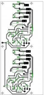
OK my comments to your design are:
You have mounted the chips near the edge of the PCB, but you'll need a heat sink, where is that going to go (or sit on)? Would it not be better if it had the PCB to sit on so you can move the assembly in one piece and not exert undure pressure on the LM3886's pins?
You have connected both Vcc+ pins on the chip, is that needed? I am gemnuinly curious because I have not bothered to connect one on mine, I could not fit in a thick trace so I thought why bother.
There are resistors and other components very very close to the chips. Considering you'd need to mount a heat sink plus a bolt+nut and tools to tighten it, I suppose you'd need some space to work around the chip.
The Zobel netowrk resistor and its coil is really almost sitiing on top of other components. Do you really want to have a coil resting on the singal inputs and other low level signal components?
The 1R resistor puzzles me, at 5-6 Amps it will be 6 volts. The regulation of the transformer will be another 8-15% so you'd be down 12 volts before you know it (ok it will be rather loud I suppose, so you would know it)")
You have mounted the chips near the edge of the PCB, but you'll need a heat sink, where is that going to go (or sit on)? Would it not be better if it had the PCB to sit on so you can move the assembly in one piece and not exert undure pressure on the LM3886's pins?
You have connected both Vcc+ pins on the chip, is that needed? I am gemnuinly curious because I have not bothered to connect one on mine, I could not fit in a thick trace so I thought why bother.
There are resistors and other components very very close to the chips. Considering you'd need to mount a heat sink plus a bolt+nut and tools to tighten it, I suppose you'd need some space to work around the chip.
The Zobel netowrk resistor and its coil is really almost sitiing on top of other components. Do you really want to have a coil resting on the singal inputs and other low level signal components?
The 1R resistor puzzles me, at 5-6 Amps it will be 6 volts. The regulation of the transformer will be another 8-15% so you'd be down 12 volts before you know it (ok it will be rather loud I suppose, so you would know it)
Although there is little need for a two-way speaker for a guitar, the idea to use an active filter is good.akis said:I only do it in the evenings after work so please feel free to shout if you spot errors.
Don't save at the wrong place however and build an active filter with dedicated op amps. It is not as simple as using a 6 dB high-pass and a 3 dB low-pass (15k||100nF leads to a flatter roll-off) at a randomly chosen 4 kHz. Many 4" mid-range drivers already run out of steam at that frequency.
You need to look at the drivers' frequency response. The crossing frequency should be chosen at a point, where both drivers are still one octave away from resonant frequencies, cone break-up and natural roll-off. Directivity should also play a role. Then model the cross-over to achieve symmetrical acoustic flanks around the crossing frequency.
On the PCB move the 100 nF decoupling caps next to the IC power pins. They make little sense on the far side of the 1000 µF caps.
Turn the 1000 µF caps around, so that they can connect to ground with the shortest possible distance between them. Use a single wire to the star-point for both caps.
When working with guitars, you should consider anti-parallel diodes across the input as overvoltage protection. Is the gain high enough for a guitar amp?
At 5-6 A the amplifier will be working at its limits.akis said:The 1R resistor puzzles me, at 5-6 Amps it will be 6 volts. The regulation of the transformer will be another 8-15% so you'd be down 12 volts before you know it
The resistors are only slowing down capacitor recharging, not current delivery from the caps to the amplifier. In fact they convert the power supply from a 6 dB to a 12 dB filter, which is a good thing in theory. Not always in practice though.
Regulation goes on top of the nominal voltage. It is not subtracted from it.
Pico,
you have confused two completely different phenomena.
Pacific's post6 is right.
Start up current to get the transformer working is a different issue and is solved a completely different way, using a soft start circuit.
Razor,
those 1r0 resistors could be replaced with 1 or 2ohm Thermistors. That way you reduce the charging currents passing through the rectifier when the Thermistors are cold and they reduce their resistance as they warm up.
pacificblue said:
At 5-6 A the amplifier will be working at its limits.
The resistors are only slowing down capacitor recharging, not current delivery from the caps to the amplifier. In fact they convert the power supply from a 6 dB to a 12 dB filter, which is a good thing in theory. Not always in practice though.
Regulation goes on top of the nominal voltage. It is not subtracted from it.
Ok please do not make it sound as if it is a good thing
Well, yes, if you have done your calculations with "on load" voltages, which is something I do not do.
Typically I say "I will have 16 VDC that will drop to 13 VDC on full load. But if I get a bigger transformer I may limit this."
Eg I just looked at a toroidal rated 9V and 2.6A. I drew 2.3 A out of it and I measured 9.47 V rms. With no load it measures 11.5 V rms. This is 21%.
As this is not bad in itself, the designer he has also added a series resistor of 1 R, in my case that'd be another 2.3 Volts dropped right there, another 21 %.
I bet if I drive a 16 Hz signal at full volume the oscilloscope would show me ripples at 50/100Hz as the caps would not be charging fast enough. I can go down stairs and try it but I can't be asked
9Vac and 2.6Aac is ~24VA.
That is a small transformer.
Expect the regulation to be >20%
Your test result @ 21% indicates that full load regulation could be ~25%.
That 2.6A transformer will have a maximum continuous DC current after a capacitor input filter of 1.3Adc. Drawing this amount of continuous DC current will make the transformer run very hot.
Reckon on <=50% of maximum rating for continuous DC current.
i.e. your 1.3Adc should be de-rated <=650mAdc continuous.
But transformers are hardy beasts.
They will easily survive a short term overload many times the continuous rating.
It will easily try to deliver 10Apk if you keep the transient short enough.
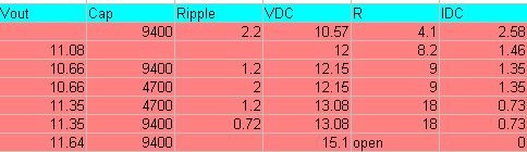
I ran some tests on that small toroidal transformer. Here is the results. I need to read some theory that will give me the ripple voltage based on filter capacitors and load etc. Anyway here it is.
The ripple voltage is peak to peak. Capacitance in uF.
As you can see, I can easily pull 2.5 Amps DC with no probs whatsoever. Ripple voltage is high at 2.2 Volts p2p with a 10.6V DC output. Not sure how useful that kind of "rectification" is, probably good enough to heat some resistors and not much else.
What is the acceptable % of ripple voltage allowable to deem a PSU well designed?
Attachments
akis said:OK my comments to your design are:
You have mounted the chips near the edge of the PCB, but you'll need a heat sink, where is that going to go (or sit on)? Would it not be better if it had the PCB to sit on so you can move the assembly in one piece and not exert undure pressure on the LM3886's pins?
This wont be problem, I'll leave same space between chip and edge of PCB.
I really don't know if this is necessary, in datasheet pins 1 and 5 are marked with V+. Does anyone know how this affects chips work? Are pins 1 and 5 internally connected?You have connected both Vcc+ pins on the chip, is that needed? I am gemnuinly curious because I have not bothered to connect one on mine, I could not fit in a thick trace so I thought why bother.
I think there will be enough space for a bolt and nut.There are resistors and other components very very close to the chips. Considering you'd need to mount a heat sink plus a bolt+nut and tools to tighten it, I suppose you'd need some space to work around the chip.
Is this going to affect the soundThe Zobel netowrk resistor and its coil is really almost sitiing on top of other components. Do you really want to have a coil resting on the singal inputs and other low level signal components?
And about 1 ohm resistor after rectifier; I 'll try experimenting: with and without it (jumper). I am not able to found 1 or 2 ohm thermistor in my country.
Will different lengths of power rails affect working of amplifier? How would you solve this on my PCB?
Thank you for all the answers!
- Status
- This old topic is closed. If you want to reopen this topic, contact a moderator using the "Report Post" button.
- Home
- Amplifiers
- Chip Amps
- My LM3886 PCB