klewis,
I started playing with CFB op amps, too. Any luck on your servo after a year? I contacted Nat Semi and they sent me right back over here. ha!
I was able to get one to work, then blew it up some how... I've been running the CFB preamp for over a year without offset compensation and not particular trouble. Someday I will put the servo back together. I'll try to post the schematic of the amp tonight.
Ken
schematic of pre amp and servo attached. The gain of the preamp is high with the values shown. I get 10v p to p as shown. As I recall, the servo is a Douglas Self design, straight out of the book... but, it works (I think).
Post your result here if it works for you. I would be interested in any improvements.
Search NS site for current feedback design literature. I believe that the AN are under the Comlinear or similar name - apparently purchased by national some time ago. Lots of helpful hints - for example to keep the feedback loop short, I put the feetback resistor on the bottom of the board, almost a direct connection between the two pins.
Good luck.
Ken
Attachments
Ken,
Did you try non-inverting vs. inverting? I took some time over the weekend to read up on CFOAs and the remarks across manufacturers was that the inverting is much lower in impedance than non-invertiing. I tried a rudimentary form of going into the inverting input and thought something was lacking.
If you had success going the inverting route, I'll go back and try it and play with my resistor values. I noticed you increased your Rfb values from the recommended 1k2 value.
I tried both, but, Mark (audioman54) strongly recomended inverting, so, I went that way. I thought it would make the servo harder to implement, but, in the end the servo worked.
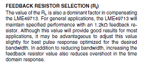
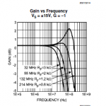
Regarding value of Rf, I've attached the application notes. Increasing Rf reduces the bandwidth slightly, I don't need 100Mhz... the notes talk about overshoot in the time domain. I took this the mean overshoot of a square wave, (maybe traditional square overshoot is in the voltage domain )which in simulation, was a problem for CF op amps. In testing my amp, I don't have overshoot.
Ken
Regarding value of Rf, I've attached the application notes. Increasing Rf reduces the bandwidth slightly, I don't need 100Mhz... the notes talk about overshoot in the time domain. I took this the mean overshoot of a square wave, (maybe traditional square overshoot is in the voltage domain
)which in simulation, was a problem for CF op amps. In testing my amp, I don't have overshoot.Ken
Attachments
I had the same thought re. the Rf value. I am definitely going to play with increasing it to see what audible gains I get through my headphones.
So I looked at the schematic and I see you went DC coupled w/o any cap in the signal chain. So the 49713 must be pretty stable for DC offset.
I have a heavily modified Aunt Corey's with BUF03's that have to be trimmed on an annual basis. I'll definitely do a bit of burn in time and see what happens to offsite under temp changes and varying V+/V- values.
I had the same thought re. the Rf value. I am definitely going to play with increasing it to see what audible gains I get through my headphones.
So I looked at the schematic and I see you went DC coupled w/o any cap in the signal chain. So the 49713 must be pretty stable for DC offset.
I think it relatively temp stable vs DC offset. The trouble is that the offset varies with Rin. So, as you turn the volume control, the offset changes. I think I'm just lucky that my volume setting doesn't produce much DC.
As I remember it, the servo was working. I can remember how I cooked it, something dumb on my part. I would recommend including the servo in your design. I made the servo as a daughter board that plugs in directly above the output section of the preamp. It keeps the traces quite short.
Ken
ok, interesting. I'll look for the same results to see what happens to DC offset with Rin.
It was busy around our home with the 3 day weekend, but I've got some parts to order and try it out with the servo. I'm putting away the 49713 cans for now for this testing because they are pricey. I ordered plenty of the soic version for experimentation just in case I do something dumb, which of course happens from time to time.
I built my proto on a breadboard with some 9 volt batteries. I put on Stereophile's recording of Rhapsody in Blue for my wife. She is not into any of this and she is just as happy with a boombox. The hairs of her arms stood on end when she heard the music coming through my HD580's. Mark and company did a really nice job on this opamp and hopefully I can squeeze the max out of it. I'll be back later to report on the servo performance.
Ken,
Please post on your experiment! I've got all parts coming in now and I've put in my order for the JLH Ripple Eater boards and I'll try them out to in this circuit.
I'm going to tinker a bit with the high pass filter on the servo. I'll build it first to your schematic, but I've got some 2.2 uF Obbligato caps I want to try. I recalculated the value of the resistor. I'm too green to know if it will make any difference at all, but that cap in the servo feedback loop I understand should be a polypropylene type. I've got some Wimas on order at .47 uF and then I'll swap them out for the Obbligatos.
- Status
- This old topic is closed. If you want to reopen this topic, contact a moderator using the "Report Post" button.
- Home
- Amplifiers
- Chip Amps
- Help with DC Servo for Current Feedback Opamp