I am currently building my first Chip Amp using the chipamp.com dual mono kit and documenting the build here.
I have just bought a couple of transformers from RS Components. I went for these . Hopefully, they're OK for my needs.
What I would like to do is use a regulated power supply. Can I simply place a separate board between the chipamp.com power supply board
and the amp board? If I can, what would the circuit need to contain?
Many thanks for any advice/recommendations provided.
")
No , not allways , you don"t really need a regulator , that transformer is a 2x25vac which will give you about 2x35vDC which is perfect for 8 ohm speakers .... Regulation would be needed for 4 ohm speakers ....
If you were to use a regulator you could run leads from the PSU board to a regulator board and then to the amp board .... Yer gonna need some heatsinks on those regulators ....
Regulators aren"t really that common in Power amps , the large power transformers usually have adequate regulation for a Poweramp not to sag to much under a load , especially if you are useing a 160Va transformer for each channel as a LM3886 will suck only about 80-100Va ... Pluss with regulation you are causeing extra heat and dropping volts which could be used for more power .... some poeple swear by regulation in power amps but I never noticed any sonic differances between the two ....
Cheers
Hi,
the 25+25Vac transformer is compatible with the National 3886 chips, if you use 8ohm speakers.
For a first amplifier project build a simple transformer, rectifier and smoothing capacitor Power Supply (PSU). Test it with a light bulb tester.
Connect the completed chipamp PCB, test again with the bulb tester.
Check output offset (mVdc) and output mVac with the input RCA shorted.
Connect your source and check the output voltages again.
Measure the output and switch off. Leave to drain the smoothing caps and measure again as you switch on.
Now connect a dummy load. Repeat your testing.
Remove the bulb tester and plug direct to the mains supply.
Check output voltages.
Switch off and finally connect your speakers. Listen.
If all is OK, complete a second channel.
Then decide whether you want to add the complication of a PSU regulator.
Three items to note from the chipamp.com site.
1.) the input has no DC blocking capacitor (=high pass filter). Be very careful to check that your sources cannot send a DC offset to this circuit.
2.) the input has no RF filter (=low pass filter). This is needed to attenuate high frequency non audio interference.
3.) the documentation refers to a snubberised PSU NOT and regulated supply.
Well, I've been reading the decimal dungeon pages which definately claim an improvement....especially with the discrete regulator circuit.some poeple swear by regulation in power amps but I never noticed any sonic differances between the two ....
The reason I'd like to use a regulator (and I understand the issue with temperature) is because I haven't selected my speakers yet. I went for 25v to cover 8 ohm speakers.
But should I go for, say, 4 or 6 ohm speakers, I'd like to be able to "tune" the power output to match the requirement of the speakers. Moreover, should I change my speakers in the future, I'd rather tweak resistor values than buy new transformers.
Or is there an easier way to achieve this flexibility without unduly impacting sound quality?
build discrete.PJPro said:Or is there an easier way to achieve this flexibility without unduly impacting sound quality?
AndrewT said:Hi,
the 25+25Vac transformer is compatible with the National 3886 chips, if you use 8ohm speakers.
For a first amplifier project build a simple transformer, rectifier and smoothing capacitor Power Supply (PSU).
I have built a couple of snubberised PSUs already using the kits from chipamp.com.
AndrewT said:
Test it with a light bulb tester.
Connect the completed chipamp PCB, test again with the bulb tester.
Check output offset (mVdc) and output mVac with the input RCA shorted.
Connect your source and check the output voltages again.
Measure the output and switch off. Leave to drain the smoothing caps and measure again as you switch on.
Now connect a dummy load. Repeat your testing.
Remove the bulb tester and plug direct to the mains supply.
Check output voltages.
Switch off and finally connect your speakers. Listen.
If all is OK, complete a second channel.
OK. Thanks for the advice.
AndrewT said:
Then decide whether you want to add the complication of a PSU regulator.
Please see my other post above. It was blocked awaiting moderation. Essentially, I would like to introduce some flexibility into the amp with regard to speaker selection. I believe that regulation of the power supply was a simple way of achieving this (for 4 & 6 ohm speakers). Is there a better way?
AndrewT said:
Three items to note from the chipamp.com site.
1.) the input has no DC blocking capacitor (=high pass filter). Be very careful to check that your sources cannot send a DC offset to this circuit.
2.) the input has no RF filter (=low pass filter). This is needed to attenuate high frequency non audio interference.
What can I do about 1 and 2? How can I add high and low pass filters into the mix? And why don't these enhancements feature in the design of the chipamp.com board? Is sound quality impacted?
Yeap, the chipamp.com PSUs are snubberised. I wondered if there was a way to insert an additional board between the chipamp.com PSU PCB and the chipamp.com amp PCB and what this additional board would require.AndrewT said:
3.) the documentation refers to a snubberised PSU NOT and regulated supply.
OK. Perhaps I'll post my own idea in the hope that it'll stimulate a bit of debate.
The schematic for the snubberised chipamp.com PSU looks like this.
This is the only schematic for the PSU on that site, although it appears to leave out the snubberising caps. When comparing this to a regulated design like the one below (from Decibel Dungeon), the similarities before the regulator are evident.
So, am I able to do something like this? Please note, I have left off the snubberising caps.
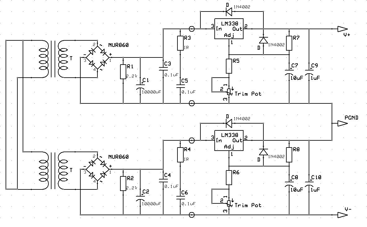
I have simply taken one of the application hints for the LM338 from its datasheet and slapped it onto the end of the snubberised chipamp.com PSU. By tweaking the values of R5, R7 and the Trimpot, one is able to adjust the level of regulation and, therefore, the voltage supplied by the PSU. Incidentally, this schematic looks remarkably like the one described by Tangent for the TREAD.
Tangent TREAD Schematic
So, am I a mile off or does this look feasible? Any comments welcomed.
The schematic for the snubberised chipamp.com PSU looks like this.
An externally hosted image should be here but it was not working when we last tested it.
This is the only schematic for the PSU on that site, although it appears to leave out the snubberising caps. When comparing this to a regulated design like the one below (from Decibel Dungeon), the similarities before the regulator are evident.
An externally hosted image should be here but it was not working when we last tested it.
So, am I able to do something like this? Please note, I have left off the snubberising caps.
I have simply taken one of the application hints for the LM338 from its datasheet and slapped it onto the end of the snubberised chipamp.com PSU. By tweaking the values of R5, R7 and the Trimpot, one is able to adjust the level of regulation and, therefore, the voltage supplied by the PSU. Incidentally, this schematic looks remarkably like the one described by Tangent for the TREAD.
Tangent TREAD Schematic
So, am I a mile off or does this look feasible? Any comments welcomed.
Interesting you should mention peak current, I've been having a go at calculating it for 50W power output driving an 8 ohm load using the equations on the data sheet. I have included the calculations in my build thread.Redshift187 said:I suspect it would work ok. My thoughts are:
a) is the 5A limit of the LM338 enough for the chip and voltage you are using? The LM3886 can peak at a little more than 6A.
b) the snubbering is probably not necessary. Voltage regulators offer some smoothing of their own.
Clicky
I make the peak current 3.5A.
If my calculations are correct, why do people go for much transformers capable of delivering 12A?
quadtech said:PJPro,
The first schematic you have has an error.
Here is the correct snubberised PSU schematic
- Prasad
Thanks for the revision.....but I can't see the difference between the two.
I got around 6.16A (with 4 ohm speakers) using the Overture Design Guide, you should check it out. It does a lot of the calculations for you.
As for transformers, I think you typically go for higher current ratings because some of the time it's idling, and some of the time it's charging the caps, which has to have higher current than if it were just a constant draw. Also, higher current transformers have better regulation, which means the unloaded voltage doesn't go too far above the load voltage. The opposite way of saying that being that the voltage doesn't "sag" as much under heavy load. In other words, you get a more consistent voltage without going to a regulated supply.
As for transformers, I think you typically go for higher current ratings because some of the time it's idling, and some of the time it's charging the caps, which has to have higher current than if it were just a constant draw. Also, higher current transformers have better regulation, which means the unloaded voltage doesn't go too far above the load voltage. The opposite way of saying that being that the voltage doesn't "sag" as much under heavy load. In other words, you get a more consistent voltage without going to a regulated supply.
PJPro said:
Thanks for the revision.....but I can't see the difference between the two.
Look at where the ground lines come out of the bridge rectifiers... in the revised one, the +PGND comes from the "left" side of the bridge, and -PGND comes from the "right" side of the bridge. You're diagram has both PGNDs coming from the "left" side of the bridge.
Hey, that's cool. Thanks.Redshift187 said:I got around 6.16A (with 4 ohm speakers) using the Overture Design Guide, you should check it out. It does a lot of the calculations for you......[snip]
Using the spreadsheet, I got 3.9A for +/- 35VDC at 8 ohm....a shade more than I calculated using the equations.
Gotcha. It's my schematic that's wrong. I was comparing the schematic quadtech posted with the chipamp.cpm schematic.Redshift187 said:
Look at where the ground lines come out of the bridge rectifiers... in the revised one, the +PGND comes from the "left" side of the bridge, and -PGND comes from the "right" side of the bridge. You're diagram has both PGNDs coming from the "left" side of the bridge.
I'll revise mine and repost.
Thanks
Do you think that my two 160VA transformers will be under powered?AndrewT said:you need more current capability because a speaker does not behave like an equivalent resistor.
- Status
- This old topic is closed. If you want to reopen this topic, contact a moderator using the "Report Post" button.
- Home
- Amplifiers
- Chip Amps
- First Lm3886