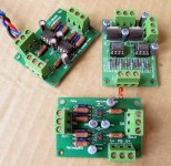
tent said:
sounds interesting.. would you be able to provide pcbs?
tent:wq
will_raymo2000 said:Put me down for Beta testing this board as well. Looks very exciting!
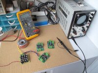
Yes,i would like provide pcbs.i have sent the UCP_v0.1 cam file to the pcb house.
P.S.
for a completed design.i have no idea about the power supply part.i will try standard fix regulated psu or batteries.
i think DC detection,RF filtering is useful function too.thanks A.T.
i do not like dc servo,it is too technical,short of human interest.
zang
Where did the buffer go?
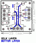
I would recommend you have to have more isolation between the screwholes and the groundplane.
Strive to have all SMD parts on the upper side, more practical.
Have the main groundplane on the solderside but you can also have groundplane on the top side but it will hardly be a better ground but it looks nice.
The hot relief pads for the connectors have very thing traces. You can have fatter hot relief at some pads you know. The ground connections could be better and you could also tune the pads size. I think they look rather big right now.
peranders said:Nice work but have you checked the trace width of the output? Very thin. I would also make the solution more compact. Put the buffer closer to the opamp.
P-A,
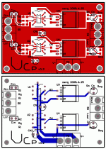
thanks for the comment.i use 20mil width track in the signal route.it is a decent value.
peranders said:Where did the buffer go?
P-A,
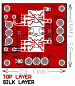
there are two design.the basical design(ucp_v0.1) is simple 2 dual opamp.the other design(ucp_0.2) is opamp gain stage with LME49600 buffer output.
Zang
peranders said:You have not 20 mils on the first design. I think you have 10-12 mils tops. You route a trace between the SO08 footprint. Check the connections to the buffer.
yes,you are riight.there are thin routes
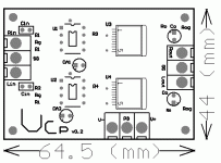
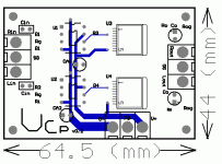
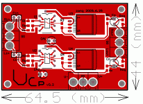
is this ok?
Attachments
peranders said:
The hot relief pads for the connectors have very thing traces.
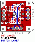
the pads for the connectors is not for hot relief.the reason i use bigger pads is for physical strong.cause it is industrial screw connectors.
i add teardrops around the pads,this is my first time use teardrops function.
i have setup grounding relief via pads near the signal input and output for better top layer grounding.
the attached is modified ucp_v0.1 smt.
Attachments
- Status
- This old topic is closed. If you want to reopen this topic, contact a moderator using the "Report Post" button.
- Home
- Amplifiers
- Chip Amps
- universal chip pre-amp project
