Hi,
I've been thinking about building this little amp for quite some time and now is the time.
I've got some quite good answer in the PSU board and here's the final verdict :
I'll use my 12-0-12VAC Transformer with 4700uF capacitor for the power supply. It should output about ±~17VCD. As I'm using 8ohm speaker, I should get about ~9-12W (as said pacificblue PSU thread) which should be fine for my use.
I'm not looking for anything fancy. I'll use this stereo amp for music/movie in a small apartment with 2 ~30years old speaker. I'm far from being an audiophile, I just want to replace the old ~30 years old FM/AM radio/amp that currently power my "sound system".
For the Amp part of the project, I'm going to build my own PCB using UV exposure method. I've just made my first test PCB with great success. I'm using a UV led box with 3:30min exposure time for my next PCB.
See :
Test PCB
From left to right : 30sec exposure to 5min
Best result
Best exposure time is the one in center : 3:30min
The smallest track is 6mil...which I think is ... great, as it etched perfectly!
Anyway,
for the PCB design, I've search the forum back and forth and found this :
lm3886 PCB
Posted by bigparsnip.
I want to use the minimum required part, but I'd like to know if this PCB need anything more to build my amplifier.
1. Do I need to add an inductance on one of the resistor ?
2. What would be the best possible resistors value for my application?
3. I'll add my own volume control on the input, but do I need any input capacitor as I've read somewhere else on the board?
4. Anything I should be aware of before etching this PCB?
As I'm still waiting for my micro drill bit & LM3886TF (x2) I'll take any advise before building anything.
Thanks a lot !
Yeah I know, but I bought the LM3886s before the transformer.
The transformer was sold as "24VAC 10A"... which I tough would be 24-0-24VAC ... but I was wrong... anyway I don't really want to waste more money on buying another transfo, I'll use this and see if it suit my need. I'll still have the possibility to upgrade later.
The transformer was sold as "24VAC 10A"... which I tough would be 24-0-24VAC ... but I was wrong... anyway I don't really want to waste more money on buying another transfo, I'll use this and see if it suit my need. I'll still have the possibility to upgrade later.
Why don't you go with LM1875? I will play awesome at that power supply and the board will be very small. Something like 1 square inch.
Later edit> I forgot to answer the questions.
1. Yes, on the output resistor you put 10 turns of AWG18 wire (10 ohm/3W in my boards).
2. If you mean feedback resistors, 22k with 1k works fine.
3. Put a capacitor between the cursor of the pot and the non-inverting input.
4. Not necessarily. You can look also for other designs or even design your own.
As I said,
I've already bought the LM3886 and transformer and don't want to spend anymore on this project.
Thanks for the answers.
As for question 2, I would like to know what value should I use for all part on the board.
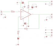
I've attached the schematic from bagparsnip design.
What would be value for R1 to R4. Same as C1 to C4.
I'm really not the "hardware guy"... My normal task is to program (which is what I'll do for my digital volume control based on a Pic or Attiny)
Thanks again!
I've already bought the LM3886 and transformer and don't want to spend anymore on this project.
Thanks for the answers.
As for question 2, I would like to know what value should I use for all part on the board.
I've attached the schematic from bagparsnip design.
What would be value for R1 to R4. Same as C1 to C4.
I'm really not the "hardware guy"... My normal task is to program (which is what I'll do for my digital volume control based on a Pic or Attiny)
Thanks again!
Attachments
Everything you need to know is in the datashetAndreq said:As for question 2, I would like to know what value should I use for all part on the board.
Tekko said:DON´T use protective earth, this will cause groundloops and other problems, the amps ground should be ISOLATED from mains ground.
You mains ground the chassi to prevent electric shock but isolate the secondary side of the transformer from it.

Don't give such advice.
 The normal and correct way is that all voltages will be connected with one end to PE in some way. There are only few exceptions, where this rule does not apply, and all of them require safety measures that most DIYers cannot provide. E. g. insulation monitoring, double insulation, protective extra-low voltage, etc.
I´ve NEVER seen an amp w anything of the secondary side connected to chassi, its always insulated from the chassi to avoid groundloops.
Usually there is no grounding @ all, just a 2prong cable.
Transformers nowdays are so well made that a event of the chassi becoming live is so unlikely that its could be called impossible.
If you make a connection of the secondary side to the chassi it should be a single wire going from the 0V rail to the chassi, preferably with a 10ohm resistor to reduce the risk of groundloops.
I´ve fried many transformers and NONE have had either the core nor the secondaries go live.
Tekko said:DON´T use protective earth, this will cause groundloops and other problems, the amps ground should be ISOLATED from mains ground.
You mains ground the chassi to prevent electric shock but isolate the secondary side of the transformer from it.
Tekko, STOP.Tekko said:I´ve NEVER seen an amp w anything of the secondary side connected to chassi, its always insulated from the chassi to avoid groundloops.
Usually there is no grounding @ all, just a 2prong cable.
Transformers nowdays are so well made that a event of the chassi becoming live is so unlikely that its could be called impossible.
If you make a connection of the secondary side to the chassi it should be a single wire going from the 0V rail to the chassi, preferably with a 10ohm resistor to reduce the risk of groundloops.
I´ve fried many transformers and NONE have had either the core nor the secondaries go live.
You have confused double insulated equipment and earthed equipment.
The information you are giving out is not just wrong, it is dangerous.
pacificblue said:
I'll take another look at the datasheet. I'm really having hard time reading all the fine prints. I mostly use datasheet for pin layout hehe.
I think I found the important information on page 20 to 22.
Thanks
p.s. Please stay on topic instead of fighting
") . I was pretty confident the Amp ground need to be connected to the star ground (earth ground).
. I was pretty confident the Amp ground need to be connected to the star ground (earth ground).So I made some calculation :
Rin = 10k
RB = 100k
Rf1 = 100k
Ri = If Gain = 15 --> 7.14K
If Gain = 20 --> 5.26K
CS = 470uF (I have 1x 4700uf on the PSU for each rail)
RM = ???K
CM = 470uf
Does that make sense ?
Ive calculated those values with :
Vopeak = ~16-17V
Ipeak = ~2A
PO = ~16 watt
Av = 11.31 (that's the minimum gain?? am I right??)
Attachments
In that schematic you should add another resistor, between non-inverting input and ground; it should have the same value as R2 and it will be the input impedance of your amplifier. R3 will have to be the same as R4. Rmute should be calculated in a way to allow the chip to draw at least 0.5mA to disable muting. The value will therefore be lowest power supply voltage divided with this current => 12V/0.5mA = 24k; 22k will be even better.
Rf should be as big as Rin. Rb should be as big as Ri. Cm depends on the switch on/off delay you want to achieve and Rm. You should add Cin and Ci. Cs should be several capacitors. 100nF X7R or better, right next to the IC, 10 µF (high ESR) near the IC, 220-1000 µF (low ESR) still on the PCB not more than 100 mm from the IC and bigger capacitors off board in the power supply.Andreq said:So I made some calculation :
Rin = 10k
RB = 100k
Rf1 = 100k
Ri = If Gain = 15 --> 7.14K
If Gain = 20 --> 5.26K
CS = 470uF (I have 1x 4700uf on the PSU for each rail)
RM = ???K
CM = 470uf
Does that make sense ?
Ive calculated those values with :
Vopeak = ~16-17V
Ipeak = ~2A
PO = ~16 watt
Av = 11.31 (that's the minimum gain?? am I right??)
(12 V - 2,6 V) / 0,5 mA = 18k8 -> 18k.ratza said:The value will therefore be lowest power supply voltage divided with this current => 12V/0.5mA = 24k; 22k will be even better.
better to keep the RF filter at the power amp input and to add an RF cap only across the RCA (or other type) input socket.Andreq said:I think I'll add the input cap & resistor directly on the input plug.
Update!
As I had some time this week, I've rebuild the PSU with a nice PCB and 4x2700uF cap (2 per rail).
here's some picture of the build and the PCB layout.
As you can probably see, I'm using an old Computer PSU enclose, this will probably be changed when I will build a wood enclose for the whole amp.
I didn't have time to look closely to the amp pcbdesign, but I think I'll do this soon, this week or the next.
edit :
And by the way, I've tested the PSU output and I get ±19.3V without load.
As I had some time this week, I've rebuild the PSU with a nice PCB and 4x2700uF cap (2 per rail).
here's some picture of the build and the PCB layout.
An externally hosted image should be here but it was not working when we last tested it.
An externally hosted image should be here but it was not working when we last tested it.
An externally hosted image should be here but it was not working when we last tested it.
An externally hosted image should be here but it was not working when we last tested it.
An externally hosted image should be here but it was not working when we last tested it.
As you can probably see, I'm using an old Computer PSU enclose, this will probably be changed when I will build a wood enclose for the whole amp.
I didn't have time to look closely to the amp pcbdesign, but I think I'll do this soon, this week or the next.
edit :
And by the way, I've tested the PSU output and I get ±19.3V without load.
Hi,
the ground plane joining the two caps nearest the output is almost continuous.
Look at the ground plane joining the two caps nearest the AC input.
Find the route that the current must follow?
The two AC connections have ruining the easiest and shortest route.
The two AC connections could have been hardwired with a twisted pair, leaving the plane intact.
You can partially repair the existing PCB by adding a hardwired link between the Zero volts terminals of the two caps.
A little question today,
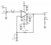
As this power amp will be connected directly to my tv output... with no tone control, would it be "ok" to add a simple passive tone control to my board ?
Something like to this :

I'll have to tweak the amp gain as I'll probably need a bit more gain with a passive tone control, but that's not really a big problem as I'm still "designing" it.
Also, any of you know a good website (in Canada if possible) to order electronic component? I know digikey and mouser, but I still find the shipping way to high compared to visiting my local electronic store (which is limited in part diversity...)
Thanks
As this power amp will be connected directly to my tv output... with no tone control, would it be "ok" to add a simple passive tone control to my board ?
Something like to this :
I'll have to tweak the amp gain as I'll probably need a bit more gain with a passive tone control, but that's not really a big problem as I'm still "designing" it.
Also, any of you know a good website (in Canada if possible) to order electronic component? I know digikey and mouser, but I still find the shipping way to high compared to visiting my local electronic store (which is limited in part diversity...)
Thanks
It seem that I've lost my helpers
Anyway, I've been working on the "Master control" today.
I'm developing it using the Arduino plartform, on a breadboard...
The final build will be directly flashed to an Atmega328.
It will use a standard Sony TV IR code as this was the simpliest to implement in the software. I might design a simple remote control schematic, pcb & software if someone need it. For my own use, I'll be using my JP1 remote control with a simple Sony 12/15 device programmed into it.
When everything is done, Ill post the final PCB layout and software code so anyone will be able to build his own.
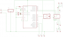
Attached is the schematic
My current proto board is somewhat different to this as it has the Arduino boot loader which use PD0 and PD1 to transmit and receive the code, but this part will not be needed when development is done.
Later, I'll add Relay control (to power on and off the amp) and the tone control if needed.
IC1: Atmega328-PU
IC2: 78L05
IC3: DS1807 (Maxim Dual Audio Digital Potentiometer)
IR1: TSOP1238 (or 1738).
Anyway, I've been working on the "Master control" today.
I'm developing it using the Arduino plartform, on a breadboard...
The final build will be directly flashed to an Atmega328.
It will use a standard Sony TV IR code as this was the simpliest to implement in the software. I might design a simple remote control schematic, pcb & software if someone need it. For my own use, I'll be using my JP1 remote control with a simple Sony 12/15 device programmed into it.
When everything is done, Ill post the final PCB layout and software code so anyone will be able to build his own.
Attached is the schematic
My current proto board is somewhat different to this as it has the Arduino boot loader which use PD0 and PD1 to transmit and receive the code, but this part will not be needed when development is done.
Later, I'll add Relay control (to power on and off the amp) and the tone control if needed.
IC1: Atmega328-PU
IC2: 78L05
IC3: DS1807 (Maxim Dual Audio Digital Potentiometer)
IR1: TSOP1238 (or 1738).
Attachments
- Status
- This old topic is closed. If you want to reopen this topic, contact a moderator using the "Report Post" button.
- Home
- Amplifiers
- Chip Amps
- My LM3886 Stereo Amp. w 12-0-12VAC Transformer