I'm planning on building a mini amplifier for testing speakers, or even boosting low level signals for other audio stuff.
IN other words, a general-purpose, HQ low-voltage amplifier for any use, for any load. Runs on a 9V or 12V battery.
The idea is to use a rail-to-rail Quad Op-Amp, parallel 2 op-amps for each stereo channel for more drive current, and drive a darlington output transistor pair with it. It will have a low gain to prevent noise pickup, and no volume control, just straight amplification.
The Plan is to use Texas Instruments TLC2274 R-T-R op-amp, since it has excellent THD% and is FET based, and can peak at 50mA output per amp.
Any input or suggestions welcome.
Attachments
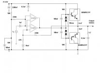
Mr Evil said:1) Do you really need to parallel two op-amps when the supply is only 12V?
2) Perhaps you could use a Sziklai pair for the output stage, configured to have a gain slightly greater than 1, for better rail efficiency.
3) There's no output capacitor on the schematic.
Thanks, you bring up some very good points.
I did forget the output capacitor for the speaker! I'll use a 1000uf coupling capacitor for the speaker. Thanks for noticing that!
The TLC2274 IC has a Max voltage of 16V. So 9-12V is a bit low, but not much. I'm not worried about the power dissipation of the IC, and I probably only need to use one output per channel, but I figured parallel amps would drive closer to the rails under higher loads if it needed more current. Also it's a quad chip, and I didn't have a use for the other 2 amps on the chip without parallel.
I did consider a Sziklai pair output, but I was trying to reduce part count by using packaged darlingtons. As far as a gain greater than 1, wouldn't that require a coupling capacitor with a resistor divider for a single rail supply?
Also, the THD of the TLC2274 is 0.0011%. Would that stay pretty constant if driving properly biased transistor outputs?
Would a Sziklai pair sound better?
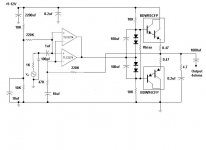
I changed a few parts values, added an input filter, and this is the updated schematic.
I'm going to heatsink these output transistors, but I have a feeling, they won't run very warm anyway.
Also, because I connected the output of the op-amps to the middle connection of the input diodes on the transistors, I'm hoping that makes the swing symmetrical, and pushes the inputs closer to the rails.
Attachments
You could reference the Sziklai pair's feedback network to the same potential divider as the op-amps are, but that wouldn't work well because the feedback resistors would be of low value, altering the reference voltage. So, on reflection, it would be more trouble than it's worth.
I don"t know if your goal is to design something yourself that will suit your purpose or to just build something yourself to suit your purpose ....
If it is the later you can very cheaply (Like $5 ) build a very simple amp useing something like the TDA2003 Power amp IC ...
It will run off of a single supply of up to 18v DC and puts out up to 10w and only uses something like 10 parts and doesn"t sound bad ... they are used in Car stereo"s ....
Just a thought ....
Cheers
Minion said:I don"t know if your goal is to design something yourself that will suit your purpose or to just build something yourself to suit your purpose ....
If it is the later you can very cheaply (Like $5 ) build a very simple amp useing something like the TDA2003 Power amp IC ...
It will run off of a single supply of up to 18v DC and puts out up to 10w and only uses something like 10 parts and doesn"t sound bad ... they are used in Car stereo"s ....
Or even TPA1517. I have a pile of these you can have for free.
The purpose was a low gain, stable amp for amplification of a weak signal, like from a headphone jack or line out. I wanted to try a different approach to Power IC chips, with gain I set myself, and also built with heavier bipolar outputs instead, and an IC socket for the IC, so I have no trouble replacing any IC chips. Most power IC chips are rated for 4A. My output transistors are 12A, and I'm not running BTL. Way overkill 
For experimentation purposes, I may drive more than just speakers with it, like maybe coils, transformers, and stuff, so I wanted solid, robust outputs. Most of the discrete parts I have are salvage anyway, so I don't mind building the amp heavy duty. I don't have to order parts from digikey for this little project, that's for sure.
I finished the soldering today and have it built.
I only tested it on a 9V DC adaptor supply for now for testing, but it worked fine. NO hum from the AC mains. I love the PSRR of the Op-amp.
Also, despite the high 220Kohm input impedance, this amp is very quiet, and isn't sensitive to noise. I get a low hum at most when touching the input, and in open air, it's silent. The Op-Amp seems more stable than a regular chipamp.
I have to change a few components. It has plenty of strong bass, but not much in clean treble, because I'm getting crossover distortion due to the low bias of the outputs running in Class B. I'm measuring only 40mA current draw from the supply for both channels + Op-Amp combined, so I'll lower the value of those resistors to increase the bias. Possibly I'll parallel a 4.7K or 3.3K on each 10K resistor.
Any ideas of a good quiescent current for each channel to run nice Class A/B for 4/2 ohm? I was guessing maybe 50mA/channel, but I'll see.
Other than that, it sounds very powerful for a low wattage amp.
The heatsink with the amp playing clipped into 4 ohms at 9V didn't even raise temp at all. It probably doesn't even need the heatsink, hehehe.
For experimentation purposes, I may drive more than just speakers with it, like maybe coils, transformers, and stuff, so I wanted solid, robust outputs. Most of the discrete parts I have are salvage anyway, so I don't mind building the amp heavy duty. I don't have to order parts from digikey for this little project, that's for sure.
I finished the soldering today and have it built.
I only tested it on a 9V DC adaptor supply for now for testing, but it worked fine. NO hum from the AC mains. I love the PSRR of the Op-amp.
Also, despite the high 220Kohm input impedance, this amp is very quiet, and isn't sensitive to noise. I get a low hum at most when touching the input, and in open air, it's silent. The Op-Amp seems more stable than a regular chipamp.
I have to change a few components. It has plenty of strong bass, but not much in clean treble, because I'm getting crossover distortion due to the low bias of the outputs running in Class B. I'm measuring only 40mA current draw from the supply for both channels + Op-Amp combined, so I'll lower the value of those resistors to increase the bias. Possibly I'll parallel a 4.7K or 3.3K on each 10K resistor.
Any ideas of a good quiescent current for each channel to run nice Class A/B for 4/2 ohm? I was guessing maybe 50mA/channel, but I'll see.
Other than that, it sounds very powerful for a low wattage amp.
The heatsink with the amp playing clipped into 4 ohms at 9V didn't even raise temp at all.
It probably doesn't even need the heatsink, hehehe.I changed my sound source, the Treble actually sounds really good, despite being underbiased. I can't hear any crossover distortion. I went through several songs I have to make sure I was not playing a low bitrate song.
The bass, and mid notes, are strong and powerful, on bass guitar notes, and drums, and with a single 4 ohm car speaker, still using only 9V, it fills the room with loud sound. I'll try both channels at the same time on 12V with two speakers later to see how loud this thing really goes. It seems the paralleled R-T-R op-amp is doing a good job of feeding the darlington transistors with some voltage swing.
Wow, it should sound real good with a bit more bias to it.
- Status
- This old topic is closed. If you want to reopen this topic, contact a moderator using the "Report Post" button.
- Home
- Amplifiers
- Chip Amps
- DIY Mini Op-amplifier for speakers and audio testing