Looking towards another project this time a speaker amp (stereo), expanding my horizons. This will be my first speaker amp, however have already conquered a CMoY, "SS" Millet, SOHAII, and a ϒ1.
There is so much info out their on this chip-amp its hard to make choices out of all the info , but also a majority of it is on the LM3875. So to start off, I want to know some basic info...
Looking at the spec-sheet (LM3886) a Vcc of 30V seems like a good compromise between running a 4 or 8 ohm load. At this point I'm not sure what speakers I want to run, but I want keep this as universal as possible and powerful enough (just in case :veryevil. At 30V, 4-ohms, the output is ~85W and at 8-ohms ~45W. I'm not looking for SPL > SQ, more interested in SQ > SPL.
However looking at some of the distortion figures, I guess what's the problems with running too high a Vcc, heat dissipation of the chip and distortion? What's a good compromise? Is it worthwhile to build a PSU, that can output 30-40V?
Next up the trafo, how big (VA)? The chip specs a max output of 135W, so a stereo setup (2x chips) would need a trafo to support a max of 270VA.... correct or too much? I see other builds specing anywhere from 160-300VA.
Finally looking at two PSU designs to choose from, the first part of chipamp.com kit (CarlosFM):
A regular "snubberized PSU", they mention with a 18V trafo the output is ~25V and with a 22V trafo is ~34V. Finally the VA rating should be 220-330VA.
Another is PSU is CarlosFM's Regulated Snubberized PSU:
Again the same basic principle, but I guess a better design as the output is now more "regulated" via the LM338. From what I read over on the site which hosts this PSU design, it did improve the sound quality of the gainclone.
Finally this PSU, which appears to be a variation of the above one (CarlosFM's Regulated Snubberized PSU), with more capacitance (37,6k uF vs. 9,4k uF):


So is it worth building, I'm kinda leaning towards it and it doesn't seem anymore difficult to build. Here he lists to use a 2x 30V 300VA trafo, so again is 250-300VA enough?
Are the secondary voltages & VA they list for both these designs the same specs as called out by manufacturers like Avel Lindberg? I remember when building my SOHAII there was talk about the listed specs were for unloaded trafo's vs. loaded.
There is so much info out their on this chip-amp its hard to make choices out of all the info
, but also a majority of it is on the LM3875. So to start off, I want to know some basic info...Looking at the spec-sheet (LM3886) a Vcc of 30V seems like a good compromise between running a 4 or 8 ohm load. At this point I'm not sure what speakers I want to run, but I want keep this as universal as possible and powerful enough (just in case :veryevil
. At 30V, 4-ohms, the output is ~85W and at 8-ohms ~45W. I'm not looking for SPL > SQ, more interested in SQ > SPL.However looking at some of the distortion figures, I guess what's the problems with running too high a Vcc, heat dissipation of the chip and distortion? What's a good compromise? Is it worthwhile to build a PSU, that can output 30-40V?
Next up the trafo, how big (VA)? The chip specs a max output of 135W, so a stereo setup (2x chips) would need a trafo to support a max of 270VA.... correct or too much? I see other builds specing anywhere from 160-300VA.
Finally looking at two PSU designs to choose from, the first part of chipamp.com kit (CarlosFM):
An externally hosted image should be here but it was not working when we last tested it.
A regular "snubberized PSU", they mention with a 18V trafo the output is ~25V and with a 22V trafo is ~34V. Finally the VA rating should be 220-330VA.
Another is PSU is CarlosFM's Regulated Snubberized PSU:
An externally hosted image should be here but it was not working when we last tested it.
Again the same basic principle, but I guess a better design as the output is now more "regulated" via the LM338. From what I read over on the site which hosts this PSU design, it did improve the sound quality of the gainclone.
Finally this PSU, which appears to be a variation of the above one (CarlosFM's Regulated Snubberized PSU), with more capacitance (37,6k uF vs. 9,4k uF):
So is it worth building, I'm kinda leaning towards it and it doesn't seem anymore difficult to build. Here he lists to use a 2x 30V 300VA trafo, so again is 250-300VA enough?
Are the secondary voltages & VA they list for both these designs the same specs as called out by manufacturers like Avel Lindberg? I remember when building my SOHAII there was talk about the listed specs were for unloaded trafo's vs. loaded.
The LM3886 is specified for ±28 V supply, when used with 4 Ohm loads and ±35 V supply, when used with 8 Ohm loads. Those figures are valid, when the amplifier is loaded. At idle the voltages may be higher. An unregulated supply will sag, when loaded. You can take advantage of that, as shown in the BPA-200 application note. There a 60 V CT transformer is used with an 8 Ohm load.bmwpowere36m3 said:However looking at some of the distortion figures, I guess what's the problems with running too high a Vcc, heat dissipation of the chip and distortion? What's a good compromise? Is it worthwhile to build a PSU, that can output 30-40V?
You should also be aware that those figures are for the unisolated package. The isolated package forces lower ratings due to worse heat dissipation.
Any rating that is bigger than the combined output power of the amplifiers should do.bmwpowere36m3 said:Next up the trafo, how big (VA)? The chip specs a max output of 135W, so a stereo setup (2x chips) would need a trafo to support a max of 270VA.... correct or too much? I see other builds specing anywhere from 160-300VA.
The general tendency is that unregulated PSUs sound more dynamic, while regulated PSUs sound more detailed.bmwpowere36m3 said:Finally looking at two PSU designs to choose from
Why don't you start with an unregulated PSU and try, if you like the sound? You can add regulation later.
Nuuk has tried both. Maybe his verdict helps you find a decision.
Transformer voltages are always given at nominal output. At idle they are higher by a certain percentage that is given as regulation.bmwpowere36m3 said:Are the secondary voltages & VA they list for both these designs the same specs as called out by manufacturers like
Rail voltages are given as ((nominal transformer voltage X 1,41) - voltage drop across rectifiers). They sag, when the power supply is loaded. Rule of thumb is 10 %. Some designers rely on that sag for overload protection.
A well designed regulated supply will not sag, but it needs a higher transformer voltage, so that the voltage before the regulator is always a few volts higher than the output voltage. That means it also needs a higher power rating, because the voltage difference between in- and output times the current is converted into heat and reduces the power that is available for the amplifier by that energy. Therefore you also need additional heatsinking for the regulators. All that together makes for a significantly higher price and bigger space requirements.
Re: Re: Building a Gainclone with LM3886 General Direction and PSU
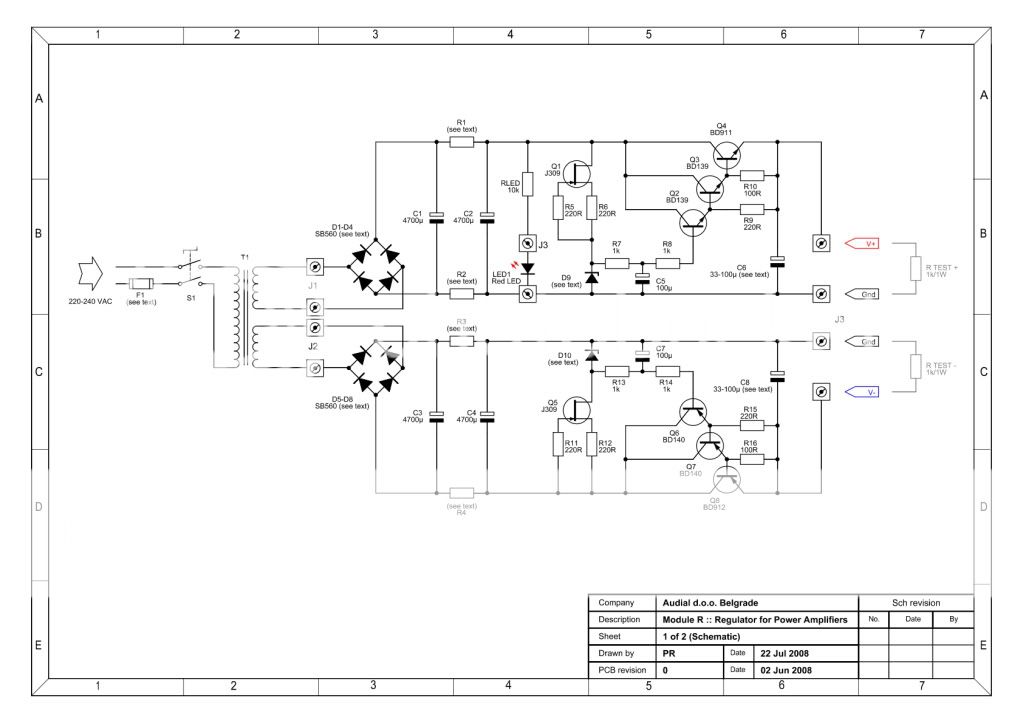
Thanks, after reading Nuuk's "journay" is says the best PSU was a discrete PSU by Pedja (Module R). After reading its description I wonder if I could use it with what I want to do?
pacificblue said:
The LM3886 is specified for ±28 V supply, when used with 4 Ohm loads and ±35 V supply, when used with 8 Ohm loads. Those figures are valid, when the amplifier is loaded. At idle the voltages may be higher. An unregulated supply will sag, when loaded. You can take advantage of that, as shown in the BPA-200 application note. There a 60 V CT transformer is used with an 8 Ohm load.
You should also be aware that those figures are for the unisolated package. The isolated package forces lower ratings due to worse heat dissipation.
Any rating that is bigger than the combined output power of the amplifiers should do.
The general tendency is that unregulated PSUs sound more dynamic, while regulated PSUs sound more detailed.
Why don't you start with an unregulated PSU and try, if you like the sound? You can add regulation later.
Nuuk has tried both. Maybe his verdict helps you find a decision.
Transformer voltages are always given at nominal output. At idle they are higher by a certain percentage that is given as regulation.
Rail voltages are given as ((nominal transformer voltage X 1,41) - voltage drop across rectifiers). They sag, when the power supply is loaded. Rule of thumb is 10 %. Some designers rely on that sag for overload protection.
A well designed regulated supply will not sag, but it needs a higher transformer voltage, so that the voltage before the regulator is always a few volts higher than the output voltage. That means it also needs a higher power rating, because the voltage difference between in- and output times the current is converted into heat and reduces the power that is available for the amplifier by that energy. Therefore you also need additional heatsinking for the regulators. All that together makes for a significantly higher price and bigger space requirements.
Thanks, after reading Nuuk's "journay" is says the best PSU was a discrete PSU by Pedja (Module R). After reading its description I wonder if I could use it with what I want to do?
pacificblue said:Yes, you can.
After reading the description, 1 board can support 30 W into a 8 ohm load (2x stereo) ~2.7 A output with a 200 VA trafo. Two boards can support 5.4 A ? with a 500VA trafo. After doing some calculations last night, if I wanted to power the LM3886 to its maximum while properly heat sinking it.... the Vcc would be 30 V and with a 4 ohm load, output ~85 W continuous, Ioutput 6.5 A. So two chips in stereo, to operate @ 85 W continuous would require a PSU capable of delivering minimum 13 A, correct? At an 8-ohm load, output ~45 W continuous, Ioutput 3.4 A. So two chips in stereo, to operate @ 45 W continuous would require a PSU capable of delivering minimum 6.8 A, correct?
Am I looking for unrealistic demands on the PSU, since from what I can tell some PSU designs (CarlosFM) are limited to 5 A due to the LM338 and even then it would be at its limit and hot.
More like looking for unrealistic demands of the LM3886.bmwpowere36m3 said:After doing some calculations last night, if I wanted to power the LM3886 to its maximum while properly heat sinking it.... the Vcc would be 30 V and with a 4 ohm load, output ~85 W continuous, Ioutput 6.5 A. So two chips in stereo, to operate @ 85 W continuous would require a PSU capable of delivering minimum 13 A, correct? At an 8-ohm load, output ~45 W continuous, Ioutput 3.4 A. So two chips in stereo, to operate @ 45 W continuous would require a PSU capable of delivering minimum 6.8 A, correct?
Am I looking for unrealistic demands on the PSU, since from what I can tell some PSU designs (CarlosFM) are limited to 5 A due to the LM338 and even then it would be at its limit and hot.
Are you going to use those amplifiers to reproduce continuous sinus waves? With a normal music signal you won't need continuous output above a few Watts.
The LM3886 is specified as 68 W into 4 Ohm for several reasons. You should not try to squeeze more out of it.
For normal music program one PSU board will be sufficient for 2 channels. Heatsinks on the MUR860s won't hurt however.
pacificblue said:
More like looking for unrealistic demands of the LM3886.
Are you going to use those amplifiers to reproduce continuous sinus waves? With a normal music signal you won't need continuous output above a few Watts.
The LM3886 is specified as 68 W into 4 Ohm for several reasons. You should not try to squeeze more out of it.
For normal music program one PSU board will be sufficient for 2 channels. Heatsinks on the MUR860s won't hurt however.
Ha ha, nope won't be playing sine waves. So in that case building it around 68W @ 4 Ω, I can go with a 25-30 V secondary trafo and a PSU with regulation to keep it anywhere from 25-30 V Vcc. The one PSU board you refer to is Pedja's Module R, correct. In which case he recommends a 200VA trafo. The reason I started thinking about it was that other designs and users have commented on 160VA trafo's being the minimum required and something around 250-300VA ideal. Would running that size trafo on one of Module R PSU's allow for more current than it can handle?
Originally posted by bmwpowere36m3
So in that case building it around 68W @ 4 Ù, I can go with a 25-30 V secondary trafo and a PSU with regulation to keep it anywhere from 25-30 V Vcc.Yes.
Those comments were probably refering to unregulated power supplies, and a lot of them rely on hearsay.Originally posted by bmwpowere36m3
users have commented on 160VA trafo's being the minimum required and something around 250-300VA ideal.
The transformer must be able to deliver the output power plus the losses in the circuit. Therefore a transformer should be at least as big as the output power.
With an unregulated power supply the losses are not too big, and there are only few and short moments, when the peak output power is actually delivered. So you could even get away with a transformer that is a bit smaller.
People like to oversize transformers to around three times that number, based on the theory that the transformer only recharges the capacitors for about 1/3 of the actual time, must therefore deliver three times the current and would work in its core saturation region then. Well-designed transformers that are designated as transformers for rectifier operation take that already into account and have a sufficient core diameter to not saturate on these conditions.
Another reason for oversizing is to keep regulation low. In the range from 160-300 V a drop from around 12% to around 8 % can be expected. No big deal.
The real reason, why oversized transformers can improve the sonic preformance is probably the temperature rise that makes saturation take place at a lower level. Transformers are usually specified for temperatures of 40-50 °C. In an amplifier enclosure the temperatures can be higher and few people conciously derate their transformers according to the temperature. Oversizing them is more or less unconcious derating.
Circuit losses are considerable, if you use a regulated power supply, so a transformer for that task must be significantly bigger than the output power. Pedja Rogic's recommendation of 200 VA seems reasonable.
The LM338's datasheet has some information on this. It says that it is "capable of supplying in excess of 5 A" and "allows current peaks of up to 12 A to be drawn for short periods of time. And it says that the LM338 comes with "thermal overload protection and safe area protection for the power transistor". There seems to be no need to worry about the LM338.Originally posted by bmwpowere36m3
Would running that size trafo on one of Module R PSU's allow for more current than it can handle?
pacificblue said:The LM338's datasheet has some information on this. It says that it is "capable of supplying in excess of 5 A" and "allows current peaks of up to 12 A to be drawn for short periods of time. And it says that the LM338 comes with "thermal overload protection and safe area protection for the power transistor". There seems to be no need to worry about the LM338.
Well the Module R PSU doesn't use a LM338, here is it's schematic:
Either way, I found a link to the source's forum: http://www.diyhifi.org/forums/viewtopic.php?f=5&t=177 So you'll figure out the details of the PSU there. Thanks again.
Now switching gears to the amp-section itself, I've been contemplating using chipamp.com's PCB for my build. My question is the integration of my headphone amp (Millet "Starving Student" Hybrid) as a preamp into the power amp section. After reading the LM3886 data sheet the implementation of the input resistance is confusing me. It says that the feedback resistance should be matched with the input resistance, i.e. the same and that the ideal input resistance is 100k minimum. By setting the feedback resistance equal to 100k it minimizing DC offsets at the output. Is this correct? Finally as I understand it the purpose of Rin is to keep the chipamp stable when there is no "preamp" or source connected. So with one connected is it still necessary to worry about it?
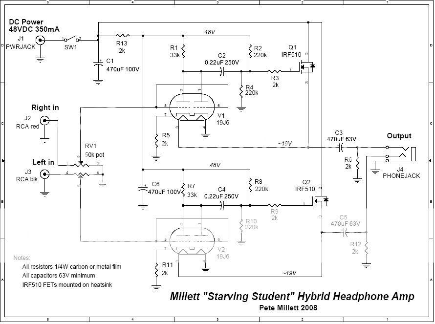
Basically this is the headphone circuit used:
and this is Chipamp.com's LM3886 Kit:
For one, I assume the output impedance of the millet is 2k, right as formed by the RC. Second I know the output capacitors are large in efforts to maintain bass when low-impedance headphones where plugged in. With the high impedance of the LM3386, they could be smaller yet preserve "bass" or bandwidth, correct?
What is the best way to couple these two sections, noting that the headphone amp will ONLY be used with the chipamp. Finally I read some suggestions as to various changes to the selected resistances and capacitors used in chipamp's PCB....
The impedances at both inputs should be the same for best common mode rejection. That means you have to put yourself in the place of each input pin and find out the total impedance of what you see. In that case you also need to take into account, what the preamp contributes to that impedance. If you do that, you will find that the chipamp schematic is not a good match for the Millett. You have to take into account the 2k resistor to ground in the Millett's output and match the feedback loop accordingly.bmwpowere36m3 said:It says that the feedback resistance should be matched with the input resistance, i.e. the same and that the ideal input resistance is 100k minimum. By setting the feedback resistance equal to 100k it minimizing DC offsets at the output. Is this correct?
The ideal value is always, what you think is the best compromise between low offset voltage at the output, high offset voltage at the input, low noise, losses, etc. It is also a question of what common mode rejection is acceptable for you and the amplifier.
The purpose of Rin is to provide a path to ground for the offset current and to provide a load with which the preamp can work stably. In some setups it also serves as a terminating resistance for the cables impedance, as snubber for the input capacitor and as attenuator.bmwpowere36m3 said:Finally as I understand it the purpose of Rin is to keep the chipamp stable when there is no "preamp" or source connected.
The output impedance is in line with the signal, so basically the IRF510's 0,54 Ohm drain-to-source resistance plus C3 plus the lead and trace impedances in the path.bmwpowere36m3 said:For one, I assume the output impedance of the millet is 2k, right as formed by the RC.
Yes. The limiting factors in that case are R6 and R12, which will maintain the load for the capacitor below 2k.bmwpowere36m3 said:Second I know the output capacitors are large in efforts to maintain bass when low-impedance headphones where plugged in. With the high impedance of the LM3386, they could be smaller yet preserve "bass" or bandwidth, correct?
If you are absolutely sure that you will never ever connect anything else than this preamp to the LM3886, skip Rin, R1 and R2 in the chipamp schmematic and connect the preamp out directly to the LM3886's pin 10. Ci should then be in the range of 1000-1500 µF to create a meaningful filter in conjunction with the actual values of C3 and R6 or C5 and R12 in the Millett.bmwpowere36m3 said:What is the best way to couple these two sections, noting that the headphone amp will ONLY be used with the chipamp. Finally I read some suggestions as to various changes to the selected resistances and capacitors used in chipamp's PCB....
If you have the slightest inkling that you may in the future decide to try different preamps or none at all, you should prepare the LM3886 to be compatible. Then you should have a look at Figure 5 on page 7 or at Figure 7 on page 21 in the LM4780's datasheet.
You should consider not to use the Millett as preamp. It provides a too high voltage level of ~19 V. Its output transistors are power transistors and are not likely to work well into high impedances. The 2k to ground in the output compels the use of too unpractical values for the LM3886's circuit to make it compatible with any thing else afterwards.
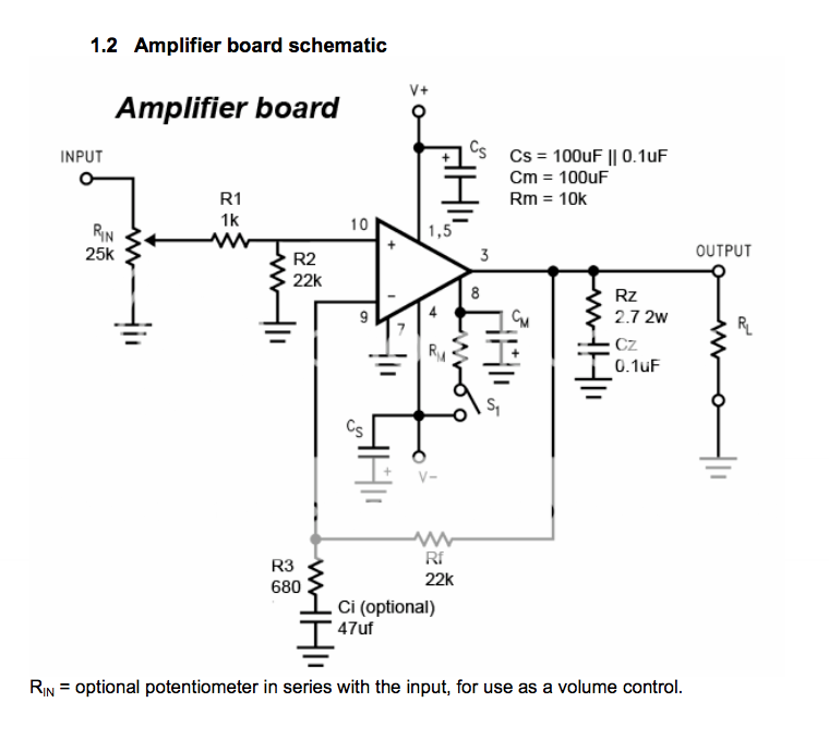
Back again, I've decided to go the simple route with the gainclone build, I have a quick question regarding the amp circuit. I'm going with the simple build like this:

My question is regarding Rg (input resistor)... I'll be using a potentiometer with this amp circuit, so I'll be feeding it from a source (Gamma1 DAC). So do I use Rg along with (in parallel) a 10k pot or just use the pot (as the input impedance)? The rest of the circuit remains the same. Thanks.
My question is regarding Rg (input resistor)... I'll be using a potentiometer with this amp circuit, so I'll be feeding it from a source (Gamma1 DAC). So do I use Rg along with (in parallel) a 10k pot or just use the pot (as the input impedance)? The rest of the circuit remains the same. Thanks.
Some of the data sheets show 20k potentiometer // 20k resistor.
However you do it, that schematic requires at least a 10k load at the input of that amplifier in order to keep DC offset low.
A 5k load, which is illustrated within your question above, results in even lower DC offset. Low DC offset is a good thing.
Point of reference:
Inappropriate DC offset occurs at 18k and higher figures for the amplifier's input load resistor, for the amplifier that's pictured in the schematic.
The fix is either to change the resistor value (of course) or to insert a capacitor in series with "RI" and this capacitor is known as "NFB cap" for its common name.
Some of the data sheets show 20k potentiometer // 20k resistor.
However you do it, that schematic requires at least a 10k load at the input of that amplifier in order to keep DC offset low.
A 5k load, which is illustrated within your question above, results in even lower DC offset. Low DC offset is a good thing.
Point of reference:
Inappropriate DC offset occurs at 18k and higher figures for the amplifier's input load resistor, for the amplifier that's pictured in the schematic.
The fix is either to change the resistor value (of course) or to insert a capacitor in series with "RI" and this capacitor is known as "NFB cap" for its common name.
That's opposite of what the National datasheet specs, " The desired input impedance is set by RIN. Very high values can cause board layout problems and DC offsets at the output. The value for the feedback resistance, Rf1, should be chosen to be a relatively large value (10 kΩ– 100 kΩ), and the other feedback resistance, Ri, is calculated using standard op amp configuration gain equations."
And since setting RIN equal to Rf1 should reduce output offset (or so it's said), that leads me to believe that RIN also should be in the range of 10-100k. I know that higher input impedances are more susceptible to noise, but make it easier for the source to drive them.
To quote Peter of AudioSector: "Use 10k"
He was talking about the input load resistor in the context of DC offset.
It is known that the source is a headphone level device owned by the creator of this thread. We don't want it to start clipping well before the potential of the power amp is reached. That source might be helpless if its load were 100k; however, if its load is 10k, then its got a chance to work right.
Ooh! That gives me an idea! Thanks!!!!
I am the creator of "that" thread. My original plans were to use a headphone amp (Millet "SS" Hybrid) as a preamp for the gainclone to add some "tube warmth." But my plans have changed, for now the gainclone will be a standalone power amp (with potentiometer) that'll I'l feed from a source (AMB Labs ϒ1 DAC). I might still experiment with a headphone amp as a preamp.
I think I found my amp design, taken from the same site:

I'm also going to get a couple of pots (10k & 50k) to experiment with. Components include: Rf 22k, Rg 680R, Rm 10k, and Cs 2200uF.
Trouble is with regulated supplies for PAs... won't they have some hysteresis, meaning will the be slow to regulate say... hf signals above a few hundred hertz, just thinking this would add distortion under certain musical conditions and power levels.... another reason why some don't use Fuses in speakers and HT lines to help keep resistances down to a bare minimum when passing 'peaky' amperes - just my thoughts.
Dave
Dave
A good voltage regulator should be able to respond to transient loads very quickly. Test it with a load resistor and a MOSFET gated by a signal generator.
Power supply circuits for modern CPUs have to supply 10s of amps at a low voltage and respond very, very quickly to transient loads. Many even need to dynamically change the output voltage for energy saving features.
Power supply circuits for modern CPUs have to supply 10s of amps at a low voltage and respond very, very quickly to transient loads. Many even need to dynamically change the output voltage for energy saving features.
- Status
- This old topic is closed. If you want to reopen this topic, contact a moderator using the "Report Post" button.
- Home
- Amplifiers
- Chip Amps
- Building a Gainclone with LM3886 General Direction and PSU