Hello oh wise DIY-ers, a newbie here. I'm following tangent's instructions for a CMOY as my first project, other than a bit of a soldering learning curve everything has gone fairly smoothly throughout assembly of power supply.
I'm at this step:
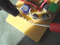
"Set your meter to DC volts, apply power to the board, and measure from the virtual ground (marked “gnd.” in the images) to the hookup wires going to the V+ and V- holes."
Sorry for the silly question, but given that ALL of this is new to me, down to using the voltage meter I just bought, can someone further explain this? Am I putting one of the probes from my meter to the ground section of the PCB and the other to one of the wires? Is it easier to use alligator clips, as touching the probe to a thin wire is a bit tough. . . .
Any and all further explanation would be gratefully appreciated, I don't want to move on to the next steps without proper testing, to save myself grief further down the line.
Thanks for letting me pollute the board with a very elementary question, all the best and happy memorial day.
I'm at this step:
"Set your meter to DC volts, apply power to the board, and measure from the virtual ground (marked “gnd.” in the images) to the hookup wires going to the V+ and V- holes."
Sorry for the silly question, but given that ALL of this is new to me, down to using the voltage meter I just bought, can someone further explain this? Am I putting one of the probes from my meter to the ground section of the PCB and the other to one of the wires? Is it easier to use alligator clips, as touching the probe to a thin wire is a bit tough. . . .
Any and all further explanation would be gratefully appreciated, I don't want to move on to the next steps without proper testing, to save myself grief further down the line.
Thanks for letting me pollute the board with a very elementary question, all the best and happy memorial day.
Exactly.clothmoth said:Am I putting one of the probes from my meter to the ground section of the PCB and the other to one of the wires?
Yes, easier and safer.clothmoth said:Is it easier to use alligator clips, as touching the probe to a thin wire is a bit tough. . . .
- Status
- This old topic is closed. If you want to reopen this topic, contact a moderator using the "Report Post" button.