Hi All,
It's been a while since my last post, anyway i recently got back in the game and built a pretty good BPA with LM4780, i'm preparing another post dedicated to it with a lot of thanks for people in here, more on that later...
In order to drive the BPA I've built a few preamps using the TIs PGA23xx devices but i can't say i'm astonished with the results. They are quite good for their price and simplicity but i'm looking to build a true audiophile preamp.
I've been reading a lot of threads in the forum about preamps and although there is plenty of info i don't have a solid idea at the moment for an excellent preamp...
I'm particularly interested in attenuation methods.
Cost is not an issue, as i'm looking to achieve the best possible result.
I had the opportunity to listen to pre amps of the likes of Dartzeel, Burmester, Einstein and a few others... i'm not trying to get to that level.. but close.")
I'll be very happy to hear your suggestions...
It's been a while since my last post, anyway i recently got back in the game and built a pretty good BPA with LM4780, i'm preparing another post dedicated to it with a lot of thanks for people in here, more on that later...
In order to drive the BPA I've built a few preamps using the TIs PGA23xx devices but i can't say i'm astonished with the results. They are quite good for their price and simplicity but i'm looking to build a true audiophile preamp.
I've been reading a lot of threads in the forum about preamps and although there is plenty of info i don't have a solid idea at the moment for an excellent preamp...
I'm particularly interested in attenuation methods.
Cost is not an issue, as i'm looking to achieve the best possible result.
I had the opportunity to listen to pre amps of the likes of Dartzeel, Burmester, Einstein and a few others... i'm not trying to get to that level.. but close.
I'll be very happy to hear your suggestions...
have a look at this thread, not all the answers, but, some good recomendations.
http://www.diyaudio.com/forums/showthread.php?s=&threadid=132471
http://www.diyaudio.com/forums/showthread.php?s=&threadid=132471
otherside said:I'm particularly interested in attenuation methods.
All the prepacked integrated solutions suck in various degrees. I have tried PGA2310, DS1666, DS1802. It is just frightening that manufacturers use these chips in pretty expensive equipment.
IME the best is a resistive attenuator with good switch and just two resistors per position. Which means either ladder or shunt attenuators. I usually choose shunt mostly for being a cheap-skate. A really nice series resistor and not so nice shunt resistors. 50% of the sound for 5% of the cost
A Shallco, Seiden or at worst Elma switch.Second best is using relays.
No experience with CMOS/Bipolar analogue switches controlling resistor dividers. Supposedly capable of very good results.
Also no experience with photoresistor based attenuators. Apparently good sounding, but high measurable distortion and extreme tweakiness repulse me.
TVCs did not work for me.
Getting the attenuator right is about 80% of a preamp. I guess the rest is 15% for PS and 5% for active circuit
An amazing number of manufacturers get this completely wrong and fit a $5 volume control into a $5k preamp. Or they just know their typical customer all too well.Thanks for the replies,
klewis thanks for the link, i've used LME49710 and it is indeed impressive, maybe slightly better than AD797... not sure, they sound very similar.
analog_sa, i've considered the resistor array approach with relays (as i need it to be remote controlled) but my concern is switching noise on every step, both mechanical and electrical...
Anyone has done something similar?
I've been reading though this lightspeed attenuator thread... but i'm not convinced... i am considering to try it at some point.
Has anyone tried the resistor attenuator with silicon analog switches? such as the ADG series from Analog?
Any other ideas are welcome.
Not sure what you mean by resistor array. Most relay attenuators use very few resistors and some logic, usually following a binary sequence. This has the advantage of very few resistors (cheap), but multiple relay contacts and resistors along the signal for some positions. And of course some positions sound better than others.
Having experimented with relays i would generally prefer to avoid them or at least use as little as possible. I also noticed that the normally closed contact sounds much better than the energised one (magnetic field?). As a test i built a ten position attenuator using ten relays controlling ten shunt resistors. You need a simple logic circuit to make sure that the signal passes through a normally closed contact only and to provide output muting. This way you get a high quality attenuator which is also quite silent compared to attenuators where multiple relays switch at the same time. Of course you will need as many relays as attenuator positions you need and a simple controller which will probably also handle the remote functions. And probably a handful of relays to audition in order to avoid disappointment.
If anyone has information of the particular type CMOS switch BAT uses i promise to immediately order it and test.
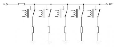
I guess this is the sort of thing you're talking about (attached).
Yes we're talking about the same thing, i just called it array because when you get high step count you need a lot of them.
I've tested a number of relays and i've found the Panasonic TXS to be quite good.
I'm considering doing some tests with the following alternative switching methods.
1. CMOS or dual supply silicon analog switches.
2. Photo MOS relays with Low CR
Problem is i don't have another attenuator to compare it with.
Attachments
otherside said:
1. CMOS or dual supply silicon analog switches.
2. Photo MOS relays with Low CR
Problem is i don't have another attenuator to compare it with.
3. Discrete bipolar transistor switches. Patented and used by Pass Labs.
I don't see the lack of an attenuator as a problem. A hard wired fixed resistor attenuator will provide a lovely comparison.
Hi Otherside,
I'm using the shunt relay attentuator approach.
http://www.diyaudio.com/forums/showthread.php?s=&threadid=107196&perpage=25&pagenumber=1
Just a little experience to share.
The close-time and open-time of a relay is not symetrical. It takes longer for a relay to move from open to close. In the case of shunt attentuator, there will be a moment that all relays are open, i.e. 0dB attentuation, or big pop! A time overlap is needed to remove this pop.
Also, the seemingly perfect isolation of relay still have about 6pF of contact capacitance. It's irrevevant for shunt attentuator, but will be a concern for channel switch.
otherside said:I've been reading a lot of threads in the forum about preamps and although there is plenty of info i don't have a solid idea at the moment for an excellent preamp...
Did you read about the Pass B1 Buffer Preamp?
http://www.diyaudio.com/forums/showthread.php?s=&threadid=124889
Hi babana,
I had a look on your project it looks very nice, however i cant believe you did all that instead of using a micro, far less expensive and much better flexibility... Anyway to the subject.
Thanks for the tip on the relays, i was quite aware of that, there are a few tricks around it.
I had a look on your thread but couldn't find the schematic sheet of the actual attenuator, would it be possible to share it with us?
Beftus thanks for the link. I've been reading parts of that huge thread about the buffer and had a good study on the website. It looks like a fantastic buffer but i'm more interested in attenuation methods at the moment.
Thanks banana for the schematic.
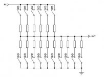
I gather that you're paralleling up resistors to get all your steps?
I've seen the THD plots but that's not always a description of what you hear.
Paralleling resistors tends to emphasize harmonics, i guess my question is can you hear any difference between the steps that require more than one set activated and the ones that use only one path?
On your THD measurements did you vary the volume?
A gain table is attached in that thread. I choosed the steps so that there are at most 4 resistors in parallel. This is to save power consumption by relays.
Upon volume changes, it's the noise floor that varies. Harmonics are basically the same. The difference is inaudible
Upon volume changes, it's the noise floor that varies. Harmonics are basically the same. The difference is inaudible
banana said:The difference is inaudible
IMO you have chosen a very complicated implementation for a modest sonic result. Which is ok if you enjoyed building it. There are much easier and more flexible ways of controlling the relays, but of course you need a microcontroller. My preference is towards simplicity and i would rather choose a single relay per step solution or a motor-driven Shallco switch.
Those must be some expensive resistors! Also, the shunt resistor is arguably at least as important as the series resistor:
http://www.diyaudio.com/forums/showthread.php?threadid=94506
http://www.diyaudio.com/forums/showthread.php?threadid=94506
- Status
- This old topic is closed. If you want to reopen this topic, contact a moderator using the "Report Post" button.
- Home
- Amplifiers
- Chip Amps
- Audiophile Preamp