I've made a prototipe amplifier with inverted LM3886. I have 21V dual secondary 300VA transformer
and 19000uF per rail for now, maybe I'll take quarter of that on the end or who knows. It is going
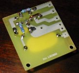
to fit in the box I have this way or the other one. I've made a tiny PCB (40x44mm) for it.
When I measured the DC offset, great, only 1.4mV, but I'am not sure if it is oscilating, because
there is 50mA drown from minus of PS, and 50 from plus with no load. I remember reading from the
datasheet that the total quiescent current is 50mA, but I'am not sure if it means 25mA from +,
and 25mA from - of PS? Otherwise it could be the oscilations that I'am not in position to detect
because I have no osciloscope.
I need some help.
Tomorrow I'll probably post a photo of PCB and the prototipe.
thanks,
mario
and 19000uF per rail for now, maybe I'll take quarter of that on the end or who knows. It is going
to fit in the box I have this way or the other one. I've made a tiny PCB (40x44mm) for it.
When I measured the DC offset, great, only 1.4mV, but I'am not sure if it is oscilating, because
there is 50mA drown from minus of PS, and 50 from plus with no load. I remember reading from the
datasheet that the total quiescent current is 50mA, but I'am not sure if it means 25mA from +,
and 25mA from - of PS? Otherwise it could be the oscilations that I'am not in position to detect
because I have no osciloscope.
I need some help.
Tomorrow I'll probably post a photo of PCB and the prototipe.
thanks,
mario
Hi, Mario
from app. note for LM3875:
Total Quiescent Power Supply
Current (VCM = 0V, VO = 0V, Io = 0 mA) tipical is 30, max. 70 mA.
You are in limits. If you wish detecting oscillation, use half wave rectifier with some signal or small shotky diode and ceramic cap ca 100nF in parallel with ca 1ME resistor and measure with multimeter on DCV range voltage on output cap 100nF. If you have reading some (when input of amp is grounded or without signal) voltage(larger than 1V) , this means that you have oscillation.
Or, simplest way, put Zobel network on output (RC 10E+100nF) and observe current, if go smaller than you have oscillation.
Regards
Re: Mmmmmm....
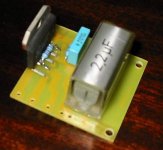
The PSU caps are hooked on the PCB with 10cm of wire.
But I think that I will follow your advice and soldier
something like 220uF per rail directly on the PCB.
tnx,
mario
carlosfm said:Where do you put the PSU caps?
No PSU caps on that circuit?
You should have something near the supply pins of the chip, or else you may have (severe) oscillation.

The PSU caps are hooked on the PCB with 10cm of wire.
But I think that I will follow your advice and soldier
something like 220uF per rail directly on the PCB.
tnx,
mario
- Status
- This old topic is closed. If you want to reopen this topic, contact a moderator using the "Report Post" button.