I'm trying to finalize my order from mouser. Can anyone let me know if this bridge rectifier would? The BOM from Jim's Audio suggests a bridge rectifier with 20A continuous forward voltage and 400V peak reverse voltage but I couldn't find any in stock at mouser. The link above is to one with 25A continuous forward voltage and 400V peak reverse voltage. I'm not sure which parameters I can deviate from, if necessary and in which direction.
Last edited:
Another part question. The BOM I have from Jim's Audio lists two 2-pin and one 3-pin terminal block with 8.5mm pitch. I have looked on Mouser, Digikey and Ebay for these and have found a total of ZERO with an 8.5mm pitch.
I just sent an email to Jim's Audio but I am extremely anxious to get this order placed. Can anyone with the Jim's Audio board please confirm that I do need 2-pin and 3-pin terminal blocks with an 8.5mm pitch?
I just sent an email to Jim's Audio but I am extremely anxious to get this order placed. Can anyone with the Jim's Audio board please confirm that I do need 2-pin and 3-pin terminal blocks with an 8.5mm pitch?
So the 5 mm pitch terminal blocks fit perfectly. The 7.5 mm pitch, 3-pin terminal block fits perfectly. The 7.5 mm pitch, 2-pin terminal block fits with some effort but I think the board is really meant for an 8.5 mm pitch block.
I have two more questions:
LED's - I really hate the fact that I have to ask questions about LED's but ... Yesterday I was assembling my blank YJ board from Jim's Audio. At the time, I wasn't sure which way to install the LED's so I tested one by touching the leads to a 9V battery. The 1st way did nothing. The 2nd way, the LED lit up but it quickly started to produce a burning smell and now does not work. This LED is what I was using. Is this LED not appropriate? If a 9V battery burnt it out, am I in trouble if I put it in the gainclone's power supply?
I think that MAYBE I messed up the lifted ground mod detailed in POST#23 but I'm not sure. Instead of soldering the ground-end of the 22K input resistor to the 10K resistor, I soldered it to the 22K (I used a 47K resistor though) feedback resistor. It looks to me like this is okay because it is part of the same node. Can anyone comment on this?
LEDs are diodes.
They block current in one direction, but not very well and will fail if reverse voltage specification is exceeded.
They pass current in the forward direction. And will keep passing current until they blow up, unless you the designer does something to prevent them blowing up.
The easy way is a resistor current limiter.
A 9V battery (or 6V or 12V) and a 1k5 resistor will allow you to safely test the orientation of most ordinary LEDs. Some do not have the flat side, indicating -ve.
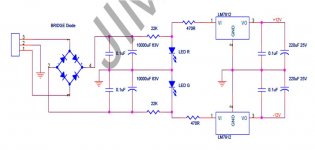
After going through the 22K resistor, the current can either 1) go through the LED's and then to ground or 2) go through another 470 ohm resistor and then to the regulator's.
FWIW, there are two LED's - a green & red - and they are mounted directly to the PCB. The red is on the negative rail and the green is on the positive rail... oohhhhh... I guess the LED's are maybe just indicators letting you know there is power on each rail? Nonetheless, my question about the 22K resistor stands.
Thanks so much for your help, AndrewT.

- Status
- This old topic is closed. If you want to reopen this topic, contact a moderator using the "Report Post" button.
- Home
- Amplifiers
- Chip Amps
- "Yuanjing" Gainclone 3886 - eBay amazing value ?