Hello
I've been working on my speakers lately and the thought of integrating the amps in the speakers have crossed my mind more then once; not only would that save space that would also cut on visible wires (which gives points for the GAF") ).
).
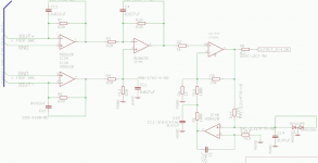
I currently have a few (16 to be exact) LM3875 that I'd like to use, the crossover will be digital (ADC -> DSP -> DACs). To save space I'd like to have a board with a DAC (PCM1792), 2 LM3875 bridged and de-coupling caps.
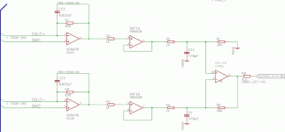
I think I've merge the I/V stage with the chip correctly (and this is where I'd like comments), is the AD8620 a good op amp for I/V ? And even more basic - is the circuit correct ? I'd really like not having to convert to single-ended but that's just "because". I'm a bit worried about offset, I haven't put any DC Servo or pots to adjust it. Maybe I'd need output relays too to make sure I don't get a start up pop.
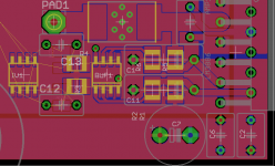
A draft of the PCB layout will be posted in my next post.
Comments are welcomed !
I've been working on my speakers lately and the thought of integrating the amps in the speakers have crossed my mind more then once; not only would that save space that would also cut on visible wires (which gives points for the GAF
). I currently have a few (16 to be exact) LM3875 that I'd like to use, the crossover will be digital (ADC -> DSP -> DACs). To save space I'd like to have a board with a DAC (PCM1792), 2 LM3875 bridged and de-coupling caps.
I think I've merge the I/V stage with the chip correctly (and this is where I'd like comments), is the AD8620 a good op amp for I/V ? And even more basic - is the circuit correct ? I'd really like not having to convert to single-ended but that's just "because". I'm a bit worried about offset, I haven't put any DC Servo or pots to adjust it. Maybe I'd need output relays too to make sure I don't get a start up pop.
A draft of the PCB layout will be posted in my next post.
Comments are welcomed !
Attachments
Hi,
I took a quick look at your circuit. The P-P current output of DAC is listed as 7.8mA into 820R this will give you a P-P voltage of 6.4V or a 2.3V RMS which is fine for the IV stange.
Not sure why you felt the buffer was required the I/V stage can drive the next stage easily.
Your next stage has a gain of 20 for a single input and since it is also an unbalancing circuit you will get a gain of 2 from this. So your gain is 40. 40 x 2.3 givs us 92V RMS. Clearly this is a problem, you will run into massive clipping at full scale.
Using a power amplifier chip to unbalance the signal is risky. It might work but the currents involved are high and the more complex the circuit them more likely that it will go unstable.
I would remove the buffers and use one of those opamps to unbalance the signal then run it into a standard single ended power amplifer implementation.
It looks like you have left off several of the control signals for the LM3886. You need to wire these up otherwise the chip won't work correctly. (Mute etc.)
The data sheet from TI shows an example circuit. Why not use that as it is worked out to be optimal for the DAC. You may need to adjust the gain slightly to match your power amplifer input. a max input voltage of 2V rms normally gives you enough headroom without wasting alot of the range of the DAC (This is assuming you are using a digital volume control, if not then you want to match the max output of the DAC to the clipping point on the amplifer)
It is here:
http://focus.ti.com/lit/ds/symlink/pcm1792.pdf
on page 37.
Regards,
Andrew
I just thought it would be nice to "isolate" the I/V stage from the power ampgfiandy said:Hi,
I took a quick look at your circuit. The P-P current output of DAC is listed as 7.8mA into 820R this will give you a P-P voltage of 6.4V or a 2.3V RMS which is fine for the IV stange.
Not sure why you felt the buffer was required the I/V stage can drive the next stage easily.
Yes, I missed that point, I was mainly working with this post. The total gain will be reduced to 24 (2x12)gfiandy said:
Your next stage has a gain of 20 for a single input and since it is also an unbalancing circuit you will get a gain of 2 from this. So your gain is 40. 40 x 2.3 givs us 92V RMS. Clearly this is a problem, you will run into massive clipping at full scale.
This is something I don't understand; aren't these chips just non-unity gain stable op-amps ? The current on the output will be the same (isn't a gain of 24 the same either it's unbalanced or not?)gfiandy said:
Using a power amplifier chip to unbalance the signal is risky. It might work but the currents involved are high and the more complex the circuit them more likely that it will go unstable.
I would remove the buffers and use one of those opamps to unbalance the signal then run it into a standard single ended power amplifer implementation.
Yes, but I'm more concerned with making it work with the LM3875 that doesn't have a mute pin. I just had a LM3886 in my library. The 2 chips are so close pin wise that it is possible to make a PCB compatible with both is nice however, the mute resistor will be added after.gfiandy said:
It looks like you have left off several of the control signals for the LM3886. You need to wire these up otherwise the chip won't work correctly. (Mute etc.)
gfiandy said:
The data sheet from TI shows an example circuit. Why not use that as it is worked out to be optimal for the DAC. You may need to adjust the gain slightly to match your power amplifer input. a max input voltage of 2V rms normally gives you enough headroom without wasting alot of the range of the DAC (This is assuming you are using a digital volume control, if not then you want to match the max output of the DAC to the clipping point on the amplifer)
It is here:
http://focus.ti.com/lit/ds/symlink/pcm1792.pdf
on page 37.
Regards,
Andrew
That's the circuit I used actually, only thing I changed is the NE5534. There won't be any volume control actually; that's the preamp's job !
I have to wait until I get back home to do the modifications, don't think I'm ignoring you
Thanks for your time and comments, I really appreciate it !
Phil
Hi,
the output from an opamp (and chipamp) is the gain times the difference between the +IN & -IN pins.
If you apply an opposite phase signal to the other pin, the difference must be twice the single input voltage from one DAC channel and it's respective buffer.
The National chip is stable for gains >=10times (+20dB).
I suspect that the stability margin is very low at this low gain.
12times (+21.6dB) is only an extra 1.6dB of gain margin.
Many builders report that the 3886 sounds better when the gain is between 20times (+26dB) and 28times (+29dB). I read this to mean that the stability margins have improved to such an extent that the improvement in stability is audible.
Hi,
I had a look at the link, I would try to find out if it worked in the end. As there is no eveidence that it actually got built and tested. It appears someone may have got an OPA541 working in this mode but this is a power opamp rather than a chip primarly designed as a audio amplifer. It has much better common mode rejection. My experience of the LM3886 and LM3875 is that whilst they are really good sounding amplifers they are not the most stable designs ever.
The problem with using a power amplifer chip like an opamp with much more current output is; as you increase the current you increase the likelyhood of the current interacting with another parts of the ciruit and creating positive feedback and hence you increase the chance of instability.
The chipamps do behave like non unitiy gain stable opamps but with large currents there are many more possibility for feedback through the power supply or parasitics. This can compromise the loop stability.
So if you really want to go ahead with this you should give yourself options in case you get instability. I would put a dominant pole option accross the feedback resistor, a capacitor and in series resistor in parallel with the feedback resistor will give you the best chance. To balance the circuit I think you should also put the same option accross the positive input resistor to ground. (Although I am not sure on this as I haven't tried to do this with a balanced circuit)
I would also recomend a RC from the output to ground (often called a Zobel network) 10nF and 100R is often used. This is often enough to stabalise an otherwise slightly unstable design.
An option for an inductor bypassed with a resistor in the output will also help if the load is at all capacitive. A few uH bypassed with 10R resistor is often used.
You may find you get away with it and don't need any of these options but adding them later is hard work. I did some work with these chips trying to implement a analogue crossover using just the opamp characterisitcs of the chip. Whilst it was possible, it took quite alot of simulation and quite alot of trial and error to get the amplifer stable.
I would also ensure you have very good local decoupling. In my experience these chips like to have a combination of a 100nF cap for high frequency decoupling and a local electrolitic cap of at least 22uF as close as possible to the power pins. This is especially important if you want to run into 4Ohms as the higher current causes even more problems.
A good start on understanding stability can be found here:
http://focus.ti.com/lit/an/sboa092a/sboa092a.pdf
Although it doen't cover the reasons amplifer stability can be compromised very well. I remeber Walt Jung did a good article on this a while ago but I can't find it online.
Regards,
Andrew
AndrewT said:Hi,
the output from an opamp (and chipamp) is the gain times the difference between the +IN & -IN pins.
If you apply an opposite phase signal to the other pin, the difference must be twice the single input voltage from one DAC channel and it's respective buffer.
The National chip is stable for gains >=10times (+20dB).
I suspect that the stability margin is very low at this low gain.
12times (+21.6dB) is only an extra 1.6dB of gain margin.
Many builders report that the 3886 sounds better when the gain is between 20times (+26dB) and 28times (+29dB). I read this to mean that the stability margins have improved to such an extent that the improvement in stability is audible.
Ah !
I knew the LM3886 was stable from +20dB but I didn't know it sounds better at +26dB. This is is news to me !
How about this: by changing R7 and R9 to 536 ohms I lower the I/V gain stage to 4.18v p-p (about 1.44vRms). Then with the power stage with a gain of 44 (2x22) I'd get about 63v at the output (full scale)
gfiandy said:Hi,
...
Regards,
Andrew
I see, you're right that it hasn't been built; I might give it a try on some protoboard but going single-ended would allow me to use the op-amp as a buffer for the signal and as DC Servo, this might be a good idea — the PCB is locally decoupled by a few caps, op-amps are powered by separate supplies.
As for the Zobel I wasn't sure- this amp will live literally inches (2-3) away from the drivers: no long cables to drive... also the load will be a simple driver with known properties (no passive XO) - think it's really required ? Well, for safety it won't harm to add it.
I really like where this is going !
Thanks !
Here's a newer version, what's new ?
- The LM3875 is now single ended
- That left 1/2 of one op amp free that I used for DC Servo
- Every component is now 1206 size
- Gain is "reasonable"
- Most part have digikey part numbers
Comments welcomed !
- The LM3875 is now single ended
- That left 1/2 of one op amp free that I used for DC Servo
- Every component is now 1206 size
- Gain is "reasonable"
- Most part have digikey part numbers
Comments welcomed !
Attachments
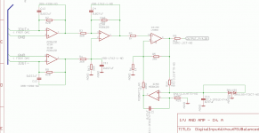
pacificblue said:Is the gain setting correct on IC4A?
Trust gfiandy about the Zobel network at the output. It is very likely necessary and in the few cases, where the LM3875/3886 can live without it, it doesn't hurt to still have it.
Ahahah I see what I did there... I'll fix IC4A :/ Damn I should trust spice a bit more
As for the Zobel network I'm still trying to figure out a place to put it -- It will be a 3 way active speaker so every board will need different values; how about a "plug-in" board ?
Hi,
You will get quite alot of Johnson thermal noise off the 2.2M resistors and whilst some of this will be smoothed out by the servo caps, some of it won't as the opamp output is a driven point it will try to drive the capacitor with the noise signal. (I think, I haven't actually done a noise analysis, if you have a simulator (or are good at math and patient) this would be worth while) To reduce this you could split the 205K resistor into 2 x 100K with a capacitor to gnd between them to filter of the the thermal noise generated. You need to be sure this filter point is at least an order of magnitude higher than the servo itself or you could get sufficient phase shift to compromise stability.
Your schematic shows no decoupling, I hope this is on a seperate sheet as it won't work without it.
Using 360R as the feedback resistor on the unbalancing opamp puts a very high current load on the output. This is likely to cause the opamp some stress and hence an increase in distortion. I would recomend using a resistor more in the 1K (more 820R resistors would be ok) region and changing the input resistors to match. It will also put quite a high load on the output of the opamp driving the -ve input channel. ( I am assuming from the previous post that you have fixed the +ve / -ve input mix up on IC 4A)
Regards,
Andrew
Unnecessary conversions between analog and digital will decrease the quality. At the least, DSP the signal before it is even converted to analog. And since you're dealing with digital, use a digital amplifier chipset. (Yes, pretty much all of them are SMD, but so are pretty much all DSPs, so I assume you have the equipment to work with SMD.)Yoshy said:Hello
I've been working on my speakers lately and the thought of integrating the amps in the speakers have crossed my mind more then once; not only would that save space that would also cut on visible wires (which gives points for the GAF
I currently have a few (16 to be exact) LM3875 that I'd like to use, the crossover will be digital (ADC -> DSP -> DACs). To save space I'd like to have a board with a DAC (PCM1792), 2 LM3875 bridged and de-coupling caps.
I think I've merge the I/V stage with the chip correctly (and this is where I'd like comments), is the AD8620 a good op amp for I/V ? And even more basic - is the circuit correct ? I'd really like not having to convert to single-ended but that's just "because". I'm a bit worried about offset, I haven't put any DC Servo or pots to adjust it. Maybe I'd need output relays too to make sure I don't get a start up pop.
A draft of the PCB layout will be posted in my next post.
Comments are welcomed !
Re: Re: Integrated DAC + Bridge LM3875 (Balanced)
What?
An analog DSP ?
I don't want to implement a crossover that has delays and an eq in full analog, ADC and DAC are good theses days...
Yes I can solder SMD no problem
star882 said:
Unnecessary conversions between analog and digital will decrease the quality. At the least, DSP the signal before it is even converted to analog. And since you're dealing with digital, use a digital amplifier chipset. (Yes, pretty much all of them are SMD, but so are pretty much all DSPs, so I assume you have the equipment to work with SMD.)
What?
An analog DSP ?
I don't want to implement a crossover that has delays and an eq in full analog, ADC and DAC are good theses days...
Yes I can solder SMD no problem
gfiandy said:Hi,
You will get quite alot of Johnson thermal noise off the 2.2M resistors and whilst some of this will be smoothed out by the servo caps, some of it won't as the opamp output is a driven point it will try to drive the capacitor with the noise signal. (I think, I haven't actually done a noise analysis, if you have a simulator (or are good at math and patient) this would be worth while) To reduce this you could split the 205K resistor into 2 x 100K with a capacitor to gnd between them to filter of the the thermal noise generated. You need to be sure this filter point is at least an order of magnitude higher than the servo itself or you could get sufficient phase shift to compromise stability.
Your schematic shows no decoupling, I hope this is on a seperate sheet as it won't work without it.
Using 360R as the feedback resistor on the unbalancing opamp puts a very high current load on the output. This is likely to cause the opamp some stress and hence an increase in distortion. I would recomend using a resistor more in the 1K (more 820R resistors would be ok) region and changing the input resistors to match. It will also put quite a high load on the output of the opamp driving the -ve input channel. ( I am assuming from the previous post that you have fixed the +ve / -ve input mix up on IC 4A)
Regards,
Andrew
Thanks Andrew for helping me out !
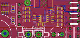
I've changed a few things in this version; as for the 2.2MEG resistors, I'm prepared to test it and if the cap doesn't help I'll just remove the DC servo. Or maybe even reduce R14 and R15 to 250k ?
Anyway the schematic is pretty messy - caps got added and removed from other sheets; Eagle doesn't seems to have a "re-annotate" function which would be more then useful right now...
C15 is the cap I added from the split of the 205k res, I was thinking about making it (along C1) 1uF
Also removed are the 360ohms resistors, replaced by 820; this will also make the cost of the amp go down which is great. Forgot to recalculate C11 and C4.
Still trying to lay it down on a PCB... Oh and yes decoupling is on another sheet, 1uF caps on every opamp per supply, X7R type
Many thanks for the comments !
Attachments
Re: Re: Re: Integrated DAC + Bridge LM3875 (Balanced)
Take the digital signal before it is converted to analog and do DSP on it, then run it to a digital amplifier chipset. Don't convert the signal to analog only to convert it back to digital.Yoshy said:What?
An analog DSP ?
I don't want to implement a crossover that has delays and an eq in full analog, ADC and DAC are good theses days...
Yes I can solder SMD no problem
Re: Re: Re: Re: Integrated DAC + Bridge LM3875 (Balanced)
I don't have a choice... It's analog out of the preamp then to amps directly and no way I'm replacing my preamp.
star882 said:
Take the digital signal before it is converted to analog and do DSP on it, then run it to a digital amplifier chipset. Don't convert the signal to analog only to convert it back to digital.
I don't have a choice... It's analog out of the preamp then to amps directly and no way I'm replacing my preamp.
Re: Re: Re: Re: Re: Integrated DAC + Bridge LM3875 (Balanced)
Converting to analog and back to digital will cause a significant loss in quality. Save the preamp for later and use a direct digital connection.Yoshy said:
I don't have a choice... It's analog out of the preamp then to amps directly and no way I'm replacing my preamp.
- Status
- This old topic is closed. If you want to reopen this topic, contact a moderator using the "Report Post" button.
- Home
- Amplifiers
- Chip Amps
- Integrated DAC + Bridge LM3875 (Balanced)