There is no DC blocking capacitor on the output.
That means there can be no leakage current passing through the non existent capacitor.
That further means you don't get any benefit from fitting a ground referencing resistor to conduct that non existent leakage to ground.
When you feed that DAC output to a Receiver, can the Receiver tolerate any DC output offset that may exist?
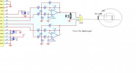
The receiver is a l20 kit version 9 its has fitted at input a HPF then LPF
with direct connection i get very good sound but very loud pops without resistor at amp input when changing tracks,the resistor to ground saves the day,had 100k before,by default
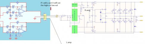
but direct connection doesn work with the pot because no highs at low volume
-so thought 1k at the out(DAC) and 1.8M at the input(amplifier)-total 1k paralel
this way between them i could add later a Preamplifier or a simple POT
with direct connection i get very good sound but very loud pops without resistor at amp input when changing tracks,the resistor to ground saves the day,had 100k before,by default
but direct connection doesn work with the pot because no highs at low volume
-so thought 1k at the out(DAC) and 1.8M at the input(amplifier)-total 1k paralel
this way between them i could add later a Preamplifier or a simple POT
If the Power Amplifier/Receiver has a DC blocking capacitor as part of the High Pass Filter then that input needs a ground referencing resistor to conduct leakage current to Signal Ground.
That could be the source of pops on switching. When the switch goes open circuit (during the switching operation) DC builds on the open contact, waiting to discharge into the next closed switch position.
It's not the DAC that is faulty, it's the PA that is wrong.
That could be the source of pops on switching. When the switch goes open circuit (during the switching operation) DC builds on the open contact, waiting to discharge into the next closed switch position.
It's not the DAC that is faulty, it's the PA that is wrong.
of course hpf formed from 10uF cap in series with res to ground to get the 16 hz i needed
and doing the same for the out of the DAC reduces the total connection impedance--with pot will be reduced further -- but whats the R1 minimum value ?
And how to get rid of that pop still have it
and doing the same for the out of the DAC reduces the total connection impedance--with pot will be reduced further -- but whats the R1 minimum value ?
And how to get rid of that pop still have it
Last edited:
you are not understanding my reply.
R1 is not required when there is no DC blocking capacitor in the Source.
A similar resistor to R1 is required in the Receiver when a DC blocking capacitor is used.
10uF and 16Hz for F-3dB. What is the Rin of the Receiver?
What type of capacitor is that 10uF? If electrolytic then that is certainly leaking and that if not fitted with a ground referencing resistor is certainly the source of the pop on switching.
The amplifier/Receiver already has the ground referencing resistor in place. That passes capacitor leakage to ground if the switch is ever opened.
You don't need a ground referencing resistor in the Source because the Source does not have a DC blocking capacitor.
BUT !!!!!!
The Source has no resistors on the outputs from the 5532. Add at least a 51r to each output right at the Pins 1 & 7.
You don't need a ground referencing resistor in the Source because the Source does not have a DC blocking capacitor.
BUT !!!!!!
The Source has no resistors on the outputs from the 5532. Add at least a 51r to each output right at the Pins 1 & 7.
ok,THANKS
found a paper after reading your advice , For high current opamps to compensate for amplifier capacitance i have to add a resistor up to 10ohm in parallel with a 3-10uH inductor
i used 5.1R + 12uH inductor ,tomorrow will search for lower values ,i think i could find 6uh
--but now im listening to it and its quite impressive ,the sound became somehow smoother
will check the frequency response later (by ear) but still very good highs and excellent mids
- Status
- This old topic is closed. If you want to reopen this topic, contact a moderator using the "Report Post" button.
- Home
- Amplifiers
- Chip Amps
- Op amps: output impedance and load resistance