hi all,
here's my end-goal:
* 8-source stereo selection
* one pga2310 per source
* microcontroller-based
i've put together and attached a schematic to show a bit more of what i mean. there is only one source (relay and pga) in the diagram now, but essentially the idea is to daisy-chain the pga's together and control them all with an atmel avr micro.
what are your suggestions for making this design better? i'm curious if optical isolation between the analog and digital grounds would improve quality, but how is it doable?
[EDIT:] oh! and do the inputs of the pga's need to be buffered and, if so, would an opa2134 be sufficient?
thanks a bunch!
~ brad.
Attachments
oh... 
aha!
well, in a flash of clarity and slight self-deprecation, i realized that there's no benefit to having a separate pga for each source. instead, just assume the design uses 8 relays into one pga, and the volume level of each source is recalled upon switching by the controlling micro.
i feel a bit silly.
still, is there anything you'd recommend to improve the design?
thanks,
~ brad.
check the data sheet on the PGA if the inputs should be buffered (I know the SSM2160 needs to be, similar VCA idea...)
anyways are you sure you want to use relays for switching your inputs? I really hate relays in the audio path, IMHO you should look into using analog switches/muxs i have used 74HCT4053 muxs with great success, actually i am currently working on an integrated amp/preamp. I should be posting with in a couple weeks. just my $0.02
Isolating grounds great idea, have the analog and digital grounds connect at one point only. You could use opto couplers from the micro to the muxs, for your digital I/O's this would keep everything seperate
Dave
It is important to drive the PGA2310 with a low source impedance. If a source impedance of greater than 600Ω is used, the distortion performance of the PGA2310 will begin to degrade.
i've attached the finished (well, nothing's ever finished...) schematic of my idea. the SN74HC595 controls the outputs of the ULN2064B darlington drivers, which supply 500mA to each relay when on. the PGA2310 is buffered by an OPA2134 opamp and takes its inputs from the relay which is currently on. ten digital I/O lines go back to a controller board, where an AVR will make this thing actually function.
please, any more thoughts?
thanks,
~ brad.
Attachments
drummer_Dave said:are you sure you want to use relays for switching your inputs? I really hate relays in the audio path, IMHO you should look into using analog switches/muxs
any reason why a relay would be unsuitable as compared to an integrated circuit?
~ brad.
Someone is doing the same thing here: http://www.arduino.cc/cgi-bin/yabb2/YaBB.pl?num=1236803143
drummer_Dave said:IMHO you should look into using analog switches/muxs i have used 74HCT4053 muxs with great success
On the contrary. Any integrated circuit, also a mux, has a high "on resistance", because the switching can only be done with semiconductors. You trade the small parasitic inductance and capacitance of a relay (or switch!) contact for the typical non-linearities of transistors and their surrounding components. E. g. the 74HCT4053 is given with 80 Ohms at 4,5 V. The lower the voltage, the higher the resistance and you rarely pass 4,5 V signals, do you?. Relays have contact resistances in the range of 0,1 Ohm and (much) below.geekysuavo said:any reason why a relay would be unsuitable as compared to an integrated circuit?
Switches must be very sophisticated and therefore expensive, if they are to be as good as relays in the signal path. Many relays, even cheap ones, come with gold-, silver- or rhodium-plated contacts for low contact and corrosion resistance. If you want a switch with those platings, the manufacturers call it 'high-end' or 'audiophile' and charge you an eye for it. You can get vacuum sealed relays and relays with inert gas filling to improve corrosion resistance and sparking even further. Some models come in metal housings for better electro-magnetic compatibility. On top of that relays are easier to integrate into a PCB and make it easier to maintain the signal path short.
Drawbacks? Yes, relays need a power supply. And you need a switch to control the relays, albeit any cheapo will do.
pacificblue i do agree with you... yes due to the larger on resistance of the mux's doing voltage switching can degrade the signal, but have you ever tried using the mux's to switch current instead? by switching the current you wont get the voltage drop across the switch... anyways it sounds better to me... but like i said just my $0.02, the audiophile business is full of controversy
Dave
P.S. I also don't like the clicking
Dave
P.S. I also don't like the clicking
zdavesf said:by switching the current you wont get the voltage drop across the switch.
Is Ohm's law in Canada different from Ohm's law in the rest of the world?
Solid state switches have their place and are quite useful, but they are rather sensitive to ESD which imply the use of additional input protection device which adds complexity.
A simple reed relay have almost no contact bounce and will last a very long time indeed.
Relays do have a so called "wetting" current this is the minimum current which needs to be switched in order to guarantee the useful life time values as detailed in the data sheet.
A small amount of contact discharge on the switching elements is required to prevent the build-up of insulating contaminants, the wetting current value will insure that the required contact discharge
will take place.
I would recommend considering this parameter since this is often the cause of failure when using relays to switch low level signals.
Join the analogue and digital grounds directly underneath the PGA,
using for example a 0805 zero Ohm link.
thanks so much for all the help! speaking of relays, is the most widely accepted method of ensuring poweron thump to place relays in the audio path between the output and speaker terminals? or, since this is a gainclone design, is it enough to simply mute the chip during turnon?
sorry for all the questions. this is my first gainclone build, so i want to make sure i do it right.
~ brad.
sorry for all the questions. this is my first gainclone build, so i want to make sure i do it right.
~ brad.
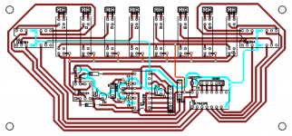
i finally got around to working out a first draft board design. attached is an image of the board with the GND net selected to illustrate that there are no groundloops and that the analog and digital grounds are connected only once: underneath the PGA. all coupling capacitors are 10uF electrolytics in parallel with 0.1uF ceramics.
please let me know if you would change anything here. the circular nature of the control lines makes me a bit nervous, but since only one of the lines between the shift register and the drivers is carrying only about 10mA DC at a time, and since the traces carrying the 500mA DC for the relay do not enclose the PGA/OPA, it shouldn't be an issue, right? (please correct me here if i'm wrong)
thanks!
~ brad.
Attachments
Hi,
Your design has no rejection to DC. So if there is any DC on the ouput of your source or the opamps you use as a buffer do not have very very good DC performance you will get Zipper noise in your volume control.
You need a resistor from the positive input to ground to provide a DC path to ground. The positive input needs this to provide its input bias current in case your source is AC coupled at its output. (Which is quite likely). Otherwise you will get a very large DC offset due the opamp trying to draw its input bias current though the ac coupling capacitor. (this will cause massive zipper noise)
You either need a DC servo or to AC couple at the input of the volume control. Or you could just accept the zipper noise as it will only do it as you change volume level.
Normally you would introduce some resistance before the opamp to protect it from static strikes and to limit turn on current into the input (this can damage some opamps the 2112 paticularly) and a cap to ground to filer off any HF noise that may be picked up from the source or from the cables.
It is also normal to have some resistance at the output of an opamp and this is paticularly true for those in the output of the 2310 if it is anything like the old CS3310. This is to isolate the amplifer from the cable capacitance which can make them unstable. Normally a resitor of 47R to 100R is used here. (I use 47R as most coax audio cables are approx 50R and this should give a better match, however this is some what moot as the bandwidth is so low. )
If you want to protect the amplifer against static strikes, diodes to the power rails should also be used, but you could just put up with this risk.
I would seperate the ground return for the PSU for the relays from the ground return for the PSU for the volume control at least back to the connector. If possible I would seperate them completely then the high current for the relay will not be interacting with the same path as the return currents for the volume control and opamps. Also I wouldluse much thicker track for the high current paths to the relays and for the return current from the relay via its gorund return.
Unless your relays have them built in; you need back EMF catch diodes on the coils of the relays or the back emf voltage from the coils will destroy the driving circuit and possibly anything else conected to the sam power rail. (this is really inportant don't leave them off, the back EMF from the coil can be hundreds of volts)
You are right it is considered poor design to surround an analogue region with a digital region. However as the signals are static when the sytem is runing you will probably get away with it. (I would move all the control and digital circuits to one side of the PCB rather than spitting it to either side)
Sorry this is so long but there is alot more to designing and laying out a good circuit than most people realise. (and this is only the basics for a comercial design there would be alot of other things required)
Regards,
Andrew
Another thing the PGA2310 will almost certainly thump when you turn it on and off even if it is muted as the power rails don't come up evenly. Unless your power amplifer is off when you turn it on you will need a mute relay at the output or put up with the thump.
Regards,
Andrew
Regards,
Andrew
thanks for all the help Andrew!
i'm not going to be doing any fades or repeated volume changes, so most likely i can live with the dc offset if it is small enough. i suppose i could place a small ceramic cap at the signal pin of each RCA input jack before connecting to the relays, if the offset is significant.
as this preamplifier/selector will be part of an integrated amplifier with the outputs of the PGA connected quite closely to the inputs of LM3886 chipamps (with 4.7k input resistors) are the output resistors still necessary?
the ULN2064 darlington drivers contain integrated suppression diodes, though their unknown Vr(max) makes me ancy. i may redesign around simple MOSFETs with 1N4004 protection diodes. as for the digital signals sent to the drivers, i'll try to get those all to one side.
good point on the separate ground returns. this is to reduce hum, correct?
thanks again!
~ brad.
glt said:I was using a pga2320 without an input cap and the DC offset at the input eventually killed it...
wow, sounds like i need to place some ceramic caps at the inputs of the OPA2134. one question... will the capacitance and the input impedance of the opamp form a high-pass rolloff at some insanely low frequency, or am i smoking too much?
thanks,
~ brad.
- Status
- This old topic is closed. If you want to reopen this topic, contact a moderator using the "Report Post" button.
- Home
- Amplifiers
- Chip Amps
- PGA2310 and Source Selection, right direction?