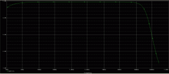
Attached is a schematic for my "Gain Clown", a composite amp using the OPA541 and OPA627. I actually have the boards on a heat sink and running - the schematic here was used in a simulation to do some final tweaking on the compensation. Simulations were very similar to the results I obtained at work using an HP4194A gain-phase analyzer. The response shows some gain peaking for smaller compensation values (100-150 pF). A compensation capacitor of 220p is about right, giving a nice, flat response curve.
In reality, the amp runs the OPA541 off of +/-30V rails, and knocks that voltage down to +/- 15V for the OPA627 using a pair of zeners.
When I get the thing wrestled into a box, I'll do some more tests, and more importantly, find out how it sounds. If anyone is interested, I'll put together a more detailed schematic.
Attachments
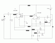
Another thing I'm considering (it's a relatively easy add) is to put a current sink between the OPA627 output to its minus rail to shift the opamp into class A operation, especially considering that its output load is the high impedance (+) input of the OPA541, a JFET-input device. This will be most likely postponed until I can audition the basic setup as-is.
Probably not too long now, I have everything mounted in a case, but I want to change the output lugs that interface the boards to the output binding posts. I'll then bring up the power supply, and t if that looks ok, hook up the amps and let rip. The amp modules have already been tested on a bench supply. Right now I'm looking at 40kuF per supply of filter caps, using 100V TO-220 Schottky rectifiers. The amp modules have 1200 uF low impedance caps (UCC LXZ series) and 2 uF polycarbonate film caps mounted right next to the power chips. I also want to change out the 220 pF compensation caps. The polystyrene units I'm using now came from my junk box, and they're pretty flimsy physically. I found some more robust caps at a local surplus store.

")
I'm reluctant to use the "m" prefix for anything except voltage. Even then, PSpice doesn't like or understand it. I'm also a slow typer, so I'm allergic to lots of zeros, especially late at night.
I was going to make a joke about stuffing the case with 40 sets of old pants kufs for damping, but there's enough silliness on this list, intentional and otherwise....
The amp will probably be completed this weekend, especially as I have tomorrow off from work. I'm kinda ambivalent as to what what I'll get, as the OPA541 seems to have been set to run with a bare minimum of bias current, but then this whole project was sort of a lark and a whim to begin with. I have a discrete amp with heavy Class A bias waiting for reassembly after some tweaks, and I wouldn't be at all surprised if it sounded better.
Yes, it does. It isn't case sensitive, so you need to be aware that m and M stand for milli, not for mega, which is meg or MEG.wrenchone said:PSpice doesn't like or understand it.
Nitpicking aside, I brought the amp up on the bench - no smoke. With 200 pF of compensation, the square wave driven overshoot is more than I would like to see in a finished amp, though it is clean, and there's no ringing. The slewing at the output square wave edges is also not monotonic - don't like that too much, either.
I try to shoot for a slightly overdamped square wave response to make sure that there is no funny business when the amp is driven hard (clipping is another matter, though - haven't tried that yet). Small signal gain-phase plots are instructive, but they don't tell the whole story. As an aside, the real world square wave response doesn't bear too much resemblance to the simulation, though the small signal frequency response plot is fairly accurate - so much for models.
I'm losing enthusiasm for this amp as I go. Since I've come this far, I'll get both channels working alike (one has a bonehead problem of some sort) and test how it sounds. I should have expected funny stuff pairing a fast opamp with a slow power stage.
Wrenchone:
Also did sims with TI TINA. (has OPA627 and OPA541 profiles)
- interesting results, especially phase and group delay over frequency.
- bummer about your actual square-wave transient tests...
- see attached link to my sim results.
Going to DeAnza electronics swap meet?
http://www.esnips.com/web/GainClown-wrenchone
I don't see anything as nice in the actual sq wave response as was indicated in your simulations. There is a fair amount of damped overshoot at the leading edges and a wrinkle about halfway up while the amp is slewing. This is with excitation with a clean sq wave with ~200 ns edges.
Andrew T - what is Jung's specific recommendations you're talking about?
I got the bonehead problems cleaned up, buttoned up the amp, and loaded it into my living room system. I's a complete change in character for my system compared to the SE screen driven amp it replaced. The amp is completely silent with no signal input - no hum, no buzz, no hiss, no nothing. I would call its character much "drier" than the tube amp it replaced. There's a small turn-on thump, but it's not too obnoxious. The next test will be whether I can stand to listen to it for extended stints. I''ll throw it back on the bench after a while, as I want to understand why the 10kHz square wave response is funky. I still think anything else I've got going in the works will probably kick its butt, but this was an idle sort of experiment anyway.
I got the bonehead problems cleaned up, buttoned up the amp, and loaded it into my living room system. I's a complete change in character for my system compared to the SE screen driven amp it replaced. The amp is completely silent with no signal input - no hum, no buzz, no hiss, no nothing. I would call its character much "drier" than the tube amp it replaced. There's a small turn-on thump, but it's not too obnoxious. The next test will be whether I can stand to listen to it for extended stints. I''ll throw it back on the bench after a while, as I want to understand why the 10kHz square wave response is funky. I still think anything else I've got going in the works will probably kick its butt, but this was an idle sort of experiment anyway.
http://www.waltjung.org/Classic_Articles.html
The lower half of the page list various references to composites.
The lower half of the page list various references to composites.
I did some looking around of my own, and the basic proviso for the composite setup is that the inner amp that is wrapped up in the feedback loop has to be much faster than the outer amp. This is pretty much obvious in retrospect. In this case, the inner amp is the 541, which is much, much slower than the 627, putting some big, fat poles in the 627's feedback loop. This explains the need for a fairly large compensation cap of 220pF around the 627. Without that cap, the composite oscillates - with too small of a value, there is a huge gain peak at high frequency ( ringing, anyone?). From the large signal response I've seen, that cap may need to be even larger to really clean things up. Anyway, the 627 lends its accuracy to the 541 (the output offset is pretty much unmeasurable on the 300 mV scale of my DVM), but it wont be boosting the speed to any significant extent. A failed experiment, this. I might be better off just cascading both opamps with separate feedback loops so that the 627 is merely a preamp, but that's no fun. I think I will try increasing the compensation cap to see its effects, and also running some distortion plots to see if the 627 helps out with what I expect would be crossover distortion from the 541, seeing as the thing doesn't appear to draw enough quiescent supply current for optimal bias in the output stage (this is assuming I have any time to reassemble our Audio Precision setup at work). I have a big, fat heat sink on this amp that is currently underutilized (barely warm after an hour of operation)- it may be interesting to add a current sink to the 541 output to push it into Class A for low level output.
- Status
- This old topic is closed. If you want to reopen this topic, contact a moderator using the "Report Post" button.
- Home
- Amplifiers
- Chip Amps
- "Gain Clown" Composite Amp