I have recently built a pair of LM3886 chipamp PCBs along with a couple of Pedja Rodic's Discrete Regulated power supplies.
I intend to house the amps, power supplies and a preamp in one case, and the transformers and bridge rectifiers in another.
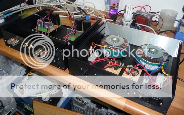
Here are some of the components I have used so far, but before I go any further I have a few questions...
Umbilicals, Earth Connection and Spade Connectors
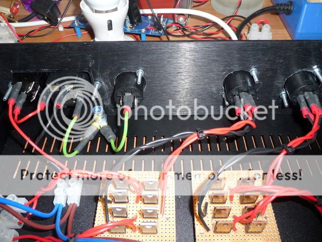
The +&- DC output from each rectifier is fed to two, four pole Speakon sockets mounted on the rear panel of the transformer case. I have a separate Speakon socket that carries the safety earth to the amplifier case. I am using 4 Core mains cable for the umbilical.
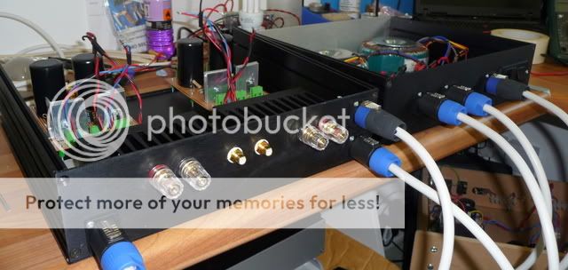
Ive used crimped spade connectors for the IEC mains inlet connections and DC output sockets (Speakon).
Are these spade connectors suitable for AC?
http://www.maplin.co.uk/module.aspx?moduleno=219181#features
The earth connection is as per Nick's diagram
http://myweb.tiscali.co.uk/nuukspot/decdun/gainclone_psu.html
Pre-amp
Towards the end of last year I built a SOAP pre-amp
http://www.diyaudio.com/forums/showthread.php?s=&threadid=122639
I plan to position the pre-amp between the two regulated power supplies, with a 50k Alps pot coupled to a shaft extension.
Do you think it will pick up any interference here, or would I be better off putting it in another case with a separate ground connection?
Star Grounding
I am right in thinking I need to connect both ground connections from each regulated ps along with both chipamp pcb (CHG) chassis grounds to the safety earth terminal?
Sorry to bombard you with so many questions!
Thanks
Richard")
I intend to house the amps, power supplies and a preamp in one case, and the transformers and bridge rectifiers in another.
Here are some of the components I have used so far, but before I go any further I have a few questions...
Umbilicals, Earth Connection and Spade Connectors
The +&- DC output from each rectifier is fed to two, four pole Speakon sockets mounted on the rear panel of the transformer case. I have a separate Speakon socket that carries the safety earth to the amplifier case. I am using 4 Core mains cable for the umbilical.
Ive used crimped spade connectors for the IEC mains inlet connections and DC output sockets (Speakon).
Are these spade connectors suitable for AC?
http://www.maplin.co.uk/module.aspx?moduleno=219181#features
The earth connection is as per Nick's diagram
http://myweb.tiscali.co.uk/nuukspot/decdun/gainclone_psu.html
Pre-amp
Towards the end of last year I built a SOAP pre-amp
http://www.diyaudio.com/forums/showthread.php?s=&threadid=122639
I plan to position the pre-amp between the two regulated power supplies, with a 50k Alps pot coupled to a shaft extension.
Do you think it will pick up any interference here, or would I be better off putting it in another case with a separate ground connection?
Star Grounding
I am right in thinking I need to connect both ground connections from each regulated ps along with both chipamp pcb (CHG) chassis grounds to the safety earth terminal?
Sorry to bombard you with so many questions!
Thanks
Richard
Hi Richard,
Earth ground really has nothing to do with PS ground, The power supply ground is actually a neutral bus and not a ground. Whether you directly connect it to earth ground or through an isolation scheme such as a thermister or resistor is entirely up to you. Just dont use the earth connection for your star ground point, use the PS ground and bring everything to it.
Bill
the ground looks fine. It may have been a better idea to use powercon connectors. They are almost identicle to speakon connectors but there are a few subtle differences.
I am using powercon for my power umbilical and as it is a 3 pole connector its is going to carry + - and gnd back to the psu.
I am using powercon for my power umbilical and as it is a 3 pole connector its is going to carry + - and gnd back to the psu.
I have a separate Speakon socket that carries the safety earth to the amplifier case
I think this would trouble some members here. You, or someone else could disconnect the amplifier safety ground by accident leavind the case ungrounded. I think the recomendation is that the power cable ground pin should be the first to connect and the last to disconnect.
Unlikely I know, but worth bearing in mind.
John
Hi,
both metal chassis will/must have a Safety Earth. OK, your layout complies. Take note of John B's caution.
All exposed conductive parts MUST be connected to Safety Earth.
My interpretation of this rule is that "fault current" must be able to pass from any exposed terminal or socket to the Safety Earth. This can be a direct wire connection or a disconnecting network.
The main Audio Star Ground (reference) can be "floating".
I recommend it be located, as near as possible, between the amplifier output, the amplifier input, the main smoothing bank and the speaker return terminal, not "at" the PSU. Ultimately this "floating" Ground Must be connected back to Safety Earth.
On a different tack,
I reckon there should be pre-smoothing done at the transformer/rectifier location to send near DC to the amp box.
Then good quality final smoothing at the amplifier.
This creates an RCRC type power supply. If the power umbilical cable has some inductance, the supply becomes RCLrC which filters the HF artifacts even better.
This separation of the smoothing demands that the amp smoothing supplies all the transient current to the amplifiers and these local caps determine the audio quality that goes to the output.
Andrew,
Good point on the separate PS scheme, using smoothing in the PS chassis.
As for the audio star ground point, we have both oversimplified the choice of location. The optimum location is highly dependent on the particular circuit topology it is supplying, such as power amps- SE- PP- fully balanced, whether the circuit uses current sensing, and whether the circuit needs a ground reference at all. Experience and trial and error are sometimes the only solution.
Best, Bill
I could be wrong, but as I see it, all amplifier require a signal return. All Speakers require a speaker return.Bill Fuss said:As for the audio star ground point, .........................and whether the circuit needs a ground reference at all.
All amplifiers will in some way connect signal return to speaker return. To me, this seems the same as saying, all amplifiers will have a reference, but maybe not.
But more importantly,
all exposed conductive parts MUST be connected to Safety Earth.
That rule can never be oversimplified.
Hi Andrew,
I'd say you're right 98%, and I totally respect your savvy and knowledge of theory. A differential power amp such as a Pass Labs X amp does not have a speaker return to the PS because the output is differential. It does need an input reference to ground though. A fully differential amp however doesn't need one, but there are very few fully differential audio circuits out there.
Bill
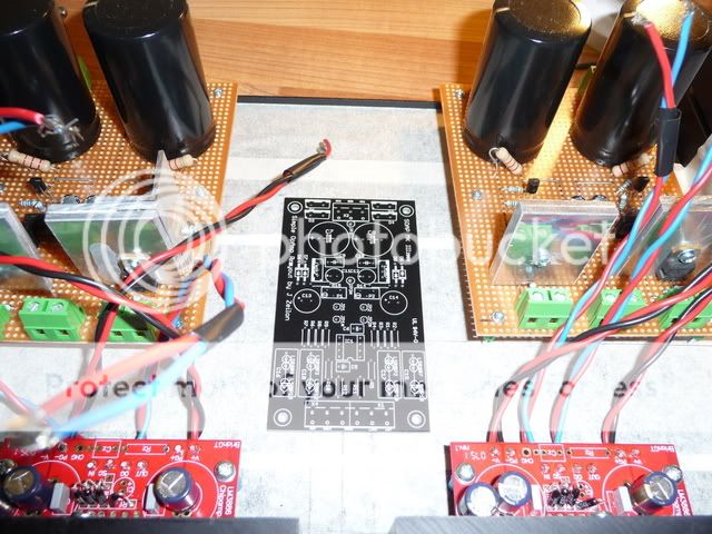
Hi Folks
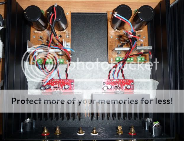
Sorry for the slow follow up...and thanks for all of your replies so far!
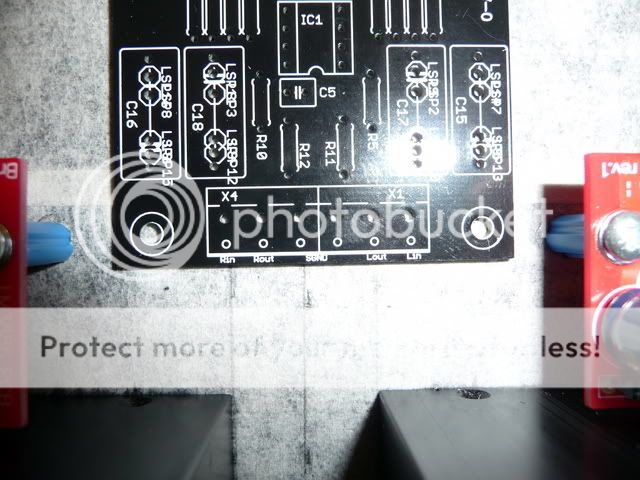
I have added a safety earth connection on the right hand side, and a star ground point in the centre.
Star Ground Hook-up wire
I have read the use of solid copper core cable is recommended for connecting the Chipamp chassis ground to the star ground point. Would you suggest using strands of solid 'twin and earth' cable?
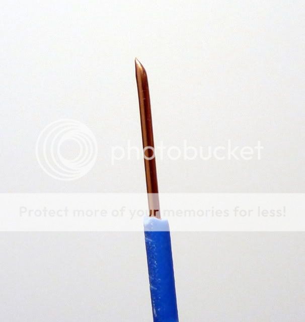
The cable diameter is just small enough to fit through the PCB holes.
And should I also use the same wire from the power supply ground connections to the star point?
Andrew, when you refer to 'smoothing' do you mean the 100uf Panasonic FC caps on the Chipamp PCB or the 100uf caps I omitted from the output of the regulated supplies?
And finally how do I add smoothing to the transformer/rectifier case?
Richard
Sorry for the slow follow up...and thanks for all of your replies so far!
I have added a safety earth connection on the right hand side, and a star ground point in the centre.
Star Ground Hook-up wire
I have read the use of solid copper core cable is recommended for connecting the Chipamp chassis ground to the star ground point. Would you suggest using strands of solid 'twin and earth' cable?
The cable diameter is just small enough to fit through the PCB holes.
And should I also use the same wire from the power supply ground connections to the star point?
Andrew, when you refer to 'smoothing' do you mean the 100uf Panasonic FC caps on the Chipamp PCB or the 100uf caps I omitted from the output of the regulated supplies?
And finally how do I add smoothing to the transformer/rectifier case?
Richard
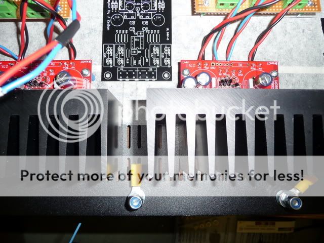
simonlarusso said:Hi Tripmaster
Looks really nice! Just a quick off topic question: where did you get your heat sinks from? I am looking for some exactly like that.
Thanks
Hi Simon
I bought the heatsinks from http://www.audiocap.co.uk/
The company had a trade stand at an Audio-jumble I attended last year.
I think they were £5 each
Richard
john blackburn said:
I think this would trouble some members here. You, or someone else could disconnect the amplifier safety ground by accident leavind the case ungrounded. I think the recomendation is that the power cable ground pin should be the first to connect and the last to disconnect.
Unlikely I know, but worth bearing in mind.
John
Hi John
Yes I know its not perfect but its all I had
 I'm going to colour code and label both plugs and their corresponding sockets.
 Richard
Bill Fuss said:Pot location shouldn't be a problem, everything is DC in there.
Nice lookin build for a chip amp, try Mauro Penasa's MyRef C next, sounds way better than it has a right to.
Bill
Hi Bill
This PRE has a built-in regulated power supply. I thought I might make use of the three unused wires in the earth umbilical...this will enable me to keep the pre-amp transformer in the main transformer case.
Is it better to locate the pot very close to the Chipamp PCBs or to the pre amp audio input/outputs?
Thanks
Richard
Hi Richard,
If you're bringing AC into the unit you are slightly compromising your design. Optimally you could rectify the supply in the other chassis and then to the umbilical. Otherwise keep the input jacks, pot and input end of the PCB as close together as possible. Running the DC supply to the front of the chassis is not a problem, and if you choose to run AC it could still be done by routing it around the perimeter.
Bill
AndrewT said:smoothing capacitors = the milliFarads (mF) after the rectifiers.
100s of uF is more usually located at the variable load and referred to as decoupling.
Hi Andrew
I suppose I could solder the smoothing capacitors to the Speakon's internal socket connections.
What value capacitor would you recommend?
I am planning to solder 100nf Wima capacitors to the legs of the rectifier diodes, I hear its supposed to reduce diode switching interferance. I'm not sure if they are going to make much of a difference but its simple and fairly cheap to try.
Thanks
Richard
Bill Fuss said:Hi Richard,
If you're bringing AC into the unit you are slightly compromising your design. Optimally you could rectify the supply in the other chassis and then to the umbilical. Otherwise keep the input jacks, pot and input end of the PCB as close together as possible. Running the DC supply to the front of the chassis is not a problem, and if you choose to run AC it could still be done by routing it around the perimeter.
Bill
Thanks Bill
I will knock up another rectifier
Richard
- Status
- This old topic is closed. If you want to reopen this topic, contact a moderator using the "Report Post" button.
- Home
- Amplifiers
- Chip Amps
- May I have some help regarding..Electrical safety,Star Grounding and Suggested Layout