Max supply voltage is ±32 V, which leads to a maximum output voltage of ~19V AC.CJ900RR said:Yes the Rsn-resistors (zobel network) should at least be 2W. But my opinion is that you dont need zobel in most cases, so you can leave them and the cap's behind out of the circut if you dont have them...
According to the datasheet 1/4 W is enough. Rule of thumb is to use resistors with 100 % safety margin, so we can only load it with 1/8 W. 4,7 Ohm needs 0,5875 V for that. The impedance of the 100 nF capacitor would have to be lower than 147,3 Ohm to achieve that voltage drop across Rsn. That is the case above ~10800 Hz. Is the supply voltage ±32 V? And if so, what could lead to continuous nominal output at 10800 Hz or above?
With 2,7 Ohm it takes 1,64 V to reach 1 W. With max supply voltage of ±38 V you get ~24 V AC out. The impedance of the 100 nF capacitor needs to fall below 36,8 Ohm for 1,64 V across the resistor. That is the case above ~43200 Hz. Sound like serious oscillation.Dxvideo said:I like LM4780s sound without the snubbers (Rsn+Csn) too. But you must try both with snubber and not.. If you decide to use them then they should be 2W or more..
Once, I fried a couple of 1W resistors in that position..
Rsn should be 1/4 W as per datasheet. If it burns, find out why and fix the fault.
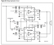
The TDA7294 works from supply voltages betwen ±10 V and ±40 V. It will not work from 12 V.ballsingtripp said:Totally sure about this one, and the supply will be 12V. I know it's kind of ridiculous, but it's just an experiment with a car battery.
pacificblue said:
The TDA7294 works from supply voltages betwen ±10 V and ±40 V. It will not work from 12 V.
Am I missing something?
The TDA7294 is designed for use with a split power supply. A battery is a single power supply.ballsingtripp said:Oh..seems strange. Does that have something to do with the battery or is that just how they're usually referred to?
The most promising amps for use with a 12 V battery are the ones designed for cars. E. g. µPC2505 for a single channel, TDA7374 or TDA8560 for two channels, TDA7560 for four channels. These are internally bridged amplifers already, so you cannot bridge them any further. There a numerous similar ICs and you will have to choose according to availability and desired output power.ballsingtripp said:Could you recommend any amps that would work?
An alternative could be a T-amp, that also come designed for 14,4 V single supplies (car battery!). They even have the advantage of being very efficient, so your battery will serve for longer listening sessions without recharging.
pacificblue said:
The TDA7294 is designed for use with a split power supply. A battery is a single power supply.
The most promising amps for use with a 12 V battery are the ones designed for cars. E. g. µPC2505 for a single channel, TDA7374 or TDA8560 for two channels, TDA7560 for four channels. These are internally bridged amplifers already, so you cannot bridge them any further. There a numerous similar ICs and you will have to choose according to availability and desired output power.
An alternative could be a T-amp, that also come designed for 14,4 V single supplies (car battery!). They even have the advantage of being very efficient, so your battery will serve for longer listening sessions without recharging.
Would the TDA8560 work for an 8 ohm load? Not much info in the data sheet, and it just says 2-4.
The T-amps look nice, but a bit too expensive for this project.

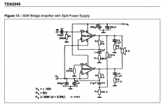
I think it would be possible to use 4 TDA2040's, two per channel bridged, for about 12 W. Their minimum supply voltage is ±2.5V, but I have no idea how it would sound.
Attachments
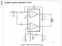
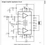
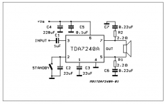
that tda schematic shows a bridged amplifier.
Pacific has already told you that you cannot bridge it again.
It also shows +-16V (=32V) supply for 30W into 8r0 @ 0.5% distortion.
If you reduce the supply to 13.8V (for a charging battery supply) the power will drop to around 6W and still with that terrible 0.5% distortion.
Pacific has already told you that you cannot bridge it again.
It also shows +-16V (=32V) supply for 30W into 8r0 @ 0.5% distortion.
If you reduce the supply to 13.8V (for a charging battery supply) the power will drop to around 6W and still with that terrible 0.5% distortion.
The TDA2040 isn't internally bridged. I'm not bridging it again, that schematic just shows two (it's a 1ch amp) as an alternative to the SE circuit.
I assumed it would be around 12W bridged with a 12V supply, since it would be about 6W single ended (according to the datasheet).
I know the distortion is pretty high, but it's the only chip I can find so far that I could bridge for over 10W with a 12V supply.
I guess it isn't possible anyway since it wouldn't be a split supply.
ballsingtripp said:it's the only chip I can find so far that I could bridge for over 10W with a 12V supply.
TDA7240
Or you could find a second-hand car amplifier from e-bay.
pacificblue said:
Awesome..I guess I didn't find it since I was searching on Newark with a supply voltage minimum.
So what about resistor wattages for that? What does the standby switch do?
Attachments
1/4 W will be sufficient.ballsingtripp said:So what about resistor wattages for that?
Turning electronic devices on and off is always stressing the components and reducing their life expextancy more than many hours of work. This amplifier also has a turn-on delay, which you would have to wait for, each time you cycle the power.ballsingtripp said:What does the standby switch do?
The stand-by switch is a possiblilty to reduce the output by 90 dB without actually switching the amplifier off. The power consumption is reduced and there will be as good as no music output.
- Status
- This old topic is closed. If you want to reopen this topic, contact a moderator using the "Report Post" button.
- Home
- Amplifiers
- Chip Amps
- Bridged LM4766 resistor wattages