Thanks you mjf!
I have made the changes you requested. The only one I'm not sure about is the 22 elcap you are talking about. it seemed to me to be connected properly. I moved the decoupling caps as close as I could to the IC. Other than this setup they would have to be on the other side of the 470uf caps in terms of the schematic. Here is a reworked version.
Thank you very much also AndrewT.
I have been working mostly on trying to get the amp PCB worked out, but I am going to tackle the transformer in just a bit. I will follow your advice and see how it goes.
Attachments
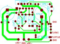
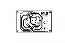
In the layout keep input and output as wide apart, as you can.
The output traces could use more flesh. The current that flows there is more or less the sum of the current in the supply rails.
The output traces are not consistent with the schematic. The speaker should be connected to the other side of the 2,7 Ohm resistor.
The mute capacitor is connected properly.
Following the instructions from both AndrewT and Pacificblue as best I could, here is the results:
NOTE: AndrewT, I didn't use a light bulb tester as I wasn't exactly sure what I was to do with it.
Primary winding:
Continuity yes
2.6 ohms res.
Secondary Windings:
Continuity Pins 1 and 7
Pins 2,3,4,5,6
Pins___Res (ohms)_____Volts
____________________
1,7---------.4-----------2.6
2,3---------.3-----------15.8
2,4---------.7-----------32.9
2,5----------1------------50
2,6---------1.3-----------66
3,4----------.3-----------16.9
3,5----------.7------------34
3,6-----------1------------50
4,5-----------.4-----------16.9
4,6-----------.7-----------32.9
5,6-----------.3------------15.8
That's what I got. I'm not sure exactly what to do with the info.
Hi,
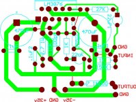
You have shared the rectifier current path to the bulk storage caps with the input ground and output ground. This is likely to cause hum.
You also should move the 100n caps closer to the amplifer there is no point in having them the far side of the bulk decoupling.
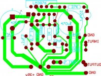
See modified layout below (done in Paint so I am sure you can do a much tidier job.)
Regards,
Andrew
You have shared the rectifier current path to the bulk storage caps with the input ground and output ground. This is likely to cause hum.
You also should move the 100n caps closer to the amplifer there is no point in having them the far side of the bulk decoupling.
See modified layout below (done in Paint so I am sure you can do a much tidier job.)
Regards,
Andrew
Attachments
jman 31 said:That's what I got. I'm not sure exactly what to do with the info.
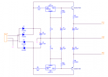
Pin 4 should become your ground pin. Pins 3 and 5 can provide the voltage for the preamplifier and 2 and 6 for the power amplifier section. They are center-tapped, i. e. use a single rectifier bridge for each pair of rails. The principle is shown in the first two diagrams here.
Pins 1 and 7 seem to be for LEDs or remote controlled potentiometer motors.
Would have been interesting to know the mains voltage during those measurements, but no need to repeat that now.
A light bulb tester means, you connect a light bulb in series to the transformer primary. That works like a current limiter in case you have a short on the secondaries. It enables you to do measurements on a faulty amplifier without destroying it and saves lots of fuses.

Andrew,
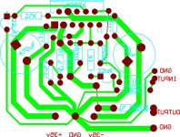
Here is another reworked schematic with almost no grounds using the same path. I moved the .1uF caps so that they are on the other side of the 470uF caps.
I now need to retrace all of the paths and make sure they are correct. Hopefully I've got it this time.
Thanks again for all the input.
Here is another reworked schematic with almost no grounds using the same path. I moved the .1uF caps so that they are on the other side of the 470uF caps.
I now need to retrace all of the paths and make sure they are correct. Hopefully I've got it this time.
Thanks again for all the input.
Attachments
pacificblue said:
Pin 4 should become your ground pin. Pins 3 and 5 can provide the voltage for the preamplifier and 2 and 6 for the power amplifier section. They are center-tapped, i. e. use a single rectifier bridge for each pair of rails. The principle is shown in the first two diagrams here.
Pins 1 and 7 seem to be for LEDs or remote controlled potentiometer motors.
Would have been interesting to know the mains voltage during those measurements, but no need to repeat that now.
A light bulb tester means, you connect a light bulb in series to the transformer primary. That works like a current limiter in case you have a short on the secondaries. It enables you to do measurements on a faulty amplifier without destroying it and saves lots of fuses.
Sorry if this is a stupid question, but can I just split that supply to run both amps? i.e. just a "Y" so to speak at the output with the secondary positive and negative terminal splitting to power both amps?
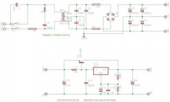
Here is the PSU I came up with based on what I could gather from the ideas that pacificblue was so kind to give me. I think the regulator resistor values will need to be adjusted to get exactly 35v, but I don't know the calculations for it so I will have to play with that some unless someone know right off hand.
Please let me know if i am way out in left field here, and none of this will even work together.
PSU Schematic
Please let me know if i am way out in left field here, and none of this will even work together.
PSU Schematic
Hi,
the regulator passes ~270mA. Combined with the 11V between input and output it will need a mighty heatsink.
What are the worst case highest and lowest input voltages. These will determine drop out and maximum heat.
The note about repeating for -ve supply cannot be used with the centre tapped transformer shown.
The two fuses between the secondary and the smoothing capacitance need to be so big to survive initial charging that they provide little protection in normal use.
The output fuses should be after the smoothing capacitors and should be F type.
The mains seems very odd.
Vcc =? Vee=? Live and Neutral are the usual names applied to the mains line connections.
Why is the switch suppression on a different line from the mains fuse?
I don't like the unsnubbered capacitors across the transformer secondary.
The mains side capacitor does not need to be snubbered. and that capacitor across the mains must be X rated.
I don't know which web site you found this misinformation on but if the rest is as bad as these examples then wipe it from your memory.
AndrewT said:Hi,
the regulator passes ~270mA. Combined with the 11V between input and output it will need a mighty heatsink.
What are the worst case highest and lowest input voltages. These will determine drop out and maximum heat.
The note about repeating for -ve supply cannot be used with the centre tapped transformer shown.
The two fuses between the secondary and the smoothing capacitance need to be so big to survive initial charging that they provide little protection in normal use.
The output fuses should be after the smoothing capacitors and should be F type.
The mains seems very odd.
Vcc =? Vee=? Live and Neutral are the usual names applied to the mains line connections.
Why is the switch suppression on a different line from the mains fuse?
I don't like the unsnubbered capacitors across the transformer secondary.
The mains side capacitor does not need to be snubbered. and that capacitor across the mains must be X rated.
I don't know which web site you found this misinformation on but if the rest is as bad as these examples then wipe it from your memory.
I don't think that the website is the problem. I'm sure it is me! I was trying to use two different ideas and make them work together. I will go back to the drawing board and see if I can come up with a better schematic. thanks for taking the time to look at it.
Westerp said:My guess is that buying a suitable transformer would be cheaper and
save time
beat a good quality used amp with the right speakers
I understand that, and I appreciate the comment. I do this as a hobby to have something to do and to learn along the way. I could go out and by a brand new amp if that was my goal. I'm not trying to be a smartass, I just want you to understand where I am coming from. I learn a lot more by doing than I do by just going out and buying the equipment. Thanks for the input though.
MJL21193 said:A better regulator circuit.
Add more pass transistors and emitter resistors in parallel to increase current. Adjust output voltage with R1 and R2.
This would hook right to the secondary of the Transformer?

- Status
- This old topic is closed. If you want to reopen this topic, contact a moderator using the "Report Post" button.
- Home
- Amplifiers
- Chip Amps
- Playback Amp