Hello.I want to put Bleeder resistors in my LM3875 but, I have seen some different values like: 2.2k,3.3k,4.7k,10k.my power supply has 20000uf per rail. I just do not like turning off my amp and still listen to music for about 20 seconds.I did not have this problem before because I had a small power supply 10uf caps but, I wanted to "feel"the bass so I put more capacitance 20000uf per rail. Now I have more bass and more music(after turning amp off lol).
My question is Which one should I use?
My question is Which one should I use?
Lower value will bleed the power quicker, however it probably won't be quick enough for your tastes. I have 15,000uF per rail in my power supply. I used 1k5 bleeder resistors (calculated the power dissipation and used resisters rated at 4 times that value). It still takes a long time to stop playing music.
Consider this. With the values I used and 27V rails, after 22.5 seconds there is still 10 volts on each rail. If you want to have the music stop when you shut the power off, bleeder resistors are not the solution. You would need too low a value to bleed that much capacitance quickly, and it would waste a lot of power (as heat).
Consider this. With the values I used and 27V rails, after 22.5 seconds there is still 10 volts on each rail. If you want to have the music stop when you shut the power off, bleeder resistors are not the solution. You would need too low a value to bleed that much capacitance quickly, and it would waste a lot of power (as heat).
you are right Redshift187,I have been playing with this issue but,I think the fastest way to cut the (Extra juice) to the speakers is using a relay but, I do not want to use a relay.I think I will leave it alone and just turn off the source first and then the amp.thank you .
What's your reason for not wanting to use a relay? A relay gadget on the speaker output also protect you seakers in case of a catstrophic chip failure, preventing DC from fyring the drivers.
In my Speaker Protect board get dealyed switch on, immidiate switvh off when AC power disappears as well as protection for DC above 0,6v in milliseconds. I have also added A/B switching function to the Speaker protection board. Right now I'm adding Clipping Indicators as well to the same board.
But maybe that's beyound your scope, so why don't you add a simple Mute function using a FET on the input, controlled by the secondary AC from your transformer! A FET, couple of diodes, a couple of resistors and a cap would fo the trick!
What's your reason for not wanting to use a relay? A relay gadget on the speaker output also protect you seakers in case of a catstrophic chip failure, preventing DC from fyring the drivers.
In my Speaker Protect board get dealyed switch on, immidiate switch off when AC power disappears as well as protection for DC above +/-0,6v in milliseconds. I have also added A/B switching function to the Speaker protection board. Right now I'm adding Clipping Indicators as well to the same board.
But maybe that's beyound your scope, so why don't you add a simple Mute function using a FET on the input, controlled by the secondary AC from your transformer! A FET, couple of diodes, a couple of resistors and a cap would fo the trick!
Segran said:What's your reason for not wanting to use a relay? A relay gadget on the speaker output also protect you seakers in case of a catstrophic chip failure, preventing DC from fyring the drivers.
In my Speaker Protect board get dealyed switch on, immidiate switvh off when AC power disappears as well as protection for DC above 0,6v in milliseconds. I have also added A/B switching function to the Speaker protection board. Right now I'm adding Clipping Indicators as well to the same board.
But maybe that's beyond your scope, so why don't you add a simple Mute function using a FET on the input, controlled by the secondary AC from your transformer! A FET, couple of diodes, a couple of resistors and a cap would fo the trick!
The problem with these options becomes apparent when you have your power supply in a separate enclosure.
I like making it "as simple and clean as possible" from input to the output. Also I do not like using fuses on the output or speaker dc blocker protection( I use fusses ONLY before the power transformers) one for the hot and one for the neutral.I know most people do not agree with me on these. But I see it this way.
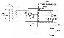
Another possibility would be to use the relay on the bleeder resistors. You can use resistors with low values, thus discharge very fast. During normal operation the resistors are disconnected, thus not wasting power and you can use a smaller power rating for them, because they only have to stand the discharge, nothing else.
E. g. to discharge 20.000 µF in ~1 s, you need a 10 Ohm resistor. If you have 30 V rails, and the resistor is always connected, it would convert 90 W of electric energy into heat. Give it the usual 100 % of safety margin and you need a resistor rated at 180 W.
When it is only connected with the amplifier switched off, it only has to withstand the energy that is stored in the capacitors for the discharge time. 20.000 µF * 30 V = 0,6 As -> 30 V * 0,6 As / 1 s = 18 W for only 1 second. A 10 W resistor could probably cope with that.
The resistor would see about 90W peak, but only for a small amount of time. At 0.46 seconds the power would be down to 10W. The resistor would handle it but if the amp were being turned on and off a lot, I would suggest using two 20R 10W resistors in parallel. Same discharge time, twice the power handling.
How would you suggest to switch the resistors into the circuit? I like this idea (it bothers me slightly that my amp takes 30 seconds to shut off too).
How would you suggest to switch the resistors into the circuit? I like this idea (it bothers me slightly that my amp takes 30 seconds to shut off too).
You could connect a relay with AC coil to the transformer secondary. The NC contact would connect the resistor to the rail.
transformer on = relay on = NC contact open = resistor not connected.
transformer off = relay off = NC contact closed = resistor connected.
The relay voltage should be similar to the transformer secondary voltage. Exact matching is not necessary, because relays usually have a wide working range. Depending on the model 20-30% below nominal voltage is good enough for them to operate.
Alternatives would be to
- use a relay with DC coil and dedicated rectifier on the transformer secondary. Maybe add a small smoothing capacitor 1 µF/mA as a nice-to-have.
- use a relay with mains voltage AC coil parallel to the transformer primary.
- connect the resistor through an auxiliary NC contact on the main switch instead of a relay.
You don't mention your rail voltage, but if it's around 27V put in some 560 ohm 5 W resistors across the caps, and similar to what AndrewT said, put a simple mute circuit on the ouput of the pre-amp. Switch the pre-amp off, the music mutes, and the 560 resistors help to pull down the power supply caps in the PA.
Mute & Bleeder
That's a great idea Andrew, Pacificblue, & Kaos. I think I'd use a 125 VAC relay connected to the power switch. Seems easier to find than any odd AC voltage relays. Use a 4 pole/double throw relay...
For AC Power off:
1) Open the mute voltage supply
2) Short the V + rail with one 400 - 600 ohm, 5 W resistor
3) Short the V- rail with another 400 - 600 ohm 5W resistor.
My small 9400 µF filter bank caused no heating in a 450 ohm 5W resistor I used to discharge the caps by hand while I was building my amp. I mean by touch, I could not feel the resistor get warmer. My point is, I think 500 ohm/5W resistors are plenty big, even for 20000 µF filter banks, if used with a relay.
Relays very often come in double throw variety. You can use the "on" energization to short out input surge-reduction resistors via the opposite contacts.
I would not bring a signal line near such a relay, though. Could pick up some 60Hz noise or switch contact noise. Make sure the energization coil is powered after the fuse.
I would not bring a signal line near such a relay, though. Could pick up some 60Hz noise or switch contact noise. Make sure the energization coil is powered after the fuse.
- Status
- This old topic is closed. If you want to reopen this topic, contact a moderator using the "Report Post" button.
- Home
- Amplifiers
- Chip Amps
- Bleeder resistor!