I have mounted four TDA1554Q on 2x6" heat-sink. It becomes very hot within 5min. I have to install this all circuit in sub-incloser. If I mount a FAN on heat-sink is that right way ?
OR
How big the heat-sink is required for those four IC ? ( I am using 12V - 5 Amp. supply )
OR
How big the heat-sink is required for those four IC ? ( I am using 12V - 5 Amp. supply )
Pd = U² / (2 * PI² * Rl)
Treat Rl as if it were 2 Ohm to compensate for the internal circuitry that gets 11 W out of 14,4 V.
I. e. 12 V and 2 Ohm -> 3,65 W / channel -> 14,6 W / IC. Assume an ambient temperature of 50 °C in the enclosure. 150 °C is the maximum permissible temperature. (150 - 50) / 14,6 = 6,85. That is the thermal resistance you need to achieve. The IC has 1 K/W, add 0,2 K/W for thermal grease. Your heatsink must remain below 6,85 - 1,2 = 5,65 K/W per IC. For four ICs it must be a quarter of that ~1,4 K/W. Something like keyword SK85 from this site.
This is assuming that you increase the power supply to double the size. With the 60 VA you have now, you can expect about half the possible output power, half the power dissipation, and a short service life, because it will be overloaded most of the time.
Thanks,
Being poor knowledge in electronics, I could not understand properly. You are requested to help in general way please.
In details.
1 IC (Stereo) 22w for Front Left woffer (20watt 4 ohm Speaker)
22w for Front Left tweeter (20watt 4 ohm)
2 IC (Stereo) 22w for Front Right woffer (20watt 4 ohm)
22w for Front Right tweeter (20watt 4 ohm)
3 IC (Stereo) 22w for rear left full range (20watt 4 ohm)
22w for rear right full range (20watt 4 ohm)
4 IC (Stereo) 22w for bass unit 1st driver 30watt 4 omh
22w for bass unit 2nd driver 30watt 4 omh
12-0-12 / 5 Amp Transformer supply.
Its sounding good for me. But I don't know how it is reliable? and I could not run this circuit more than 15 min continuesly.
I don't think it is overheating, but I wish to keep it as possible as cool the heat-sink.
If I add fan on the heat sink inside the bass incloser, it may disturb the bass wave ? Pl. help again.
10"x4" is what you need, and a fan is also desirable to keep heat in check ")
PB has the best suggestion - if you can't understand it maybe you need to read a little more - try Decibel Dungeon. And Rod Eliot's ESP website. Both excellent references.
2"x5" is too small for anything, try the one PB has linked to as a guideline for something you can get locally. You can also use a fan, sometimes the effects are quite dramatic. You need to have a secondary supply for the fan, preferably with a separate transformer, to keep electrical noise out of the audio system.
If you want help, you should be more precise. A "12 V - 5 Amp. supply" is different from a "12-0-12 / 5 Amp Transformer supply". The first tells us you have 12 V rails and 60 VA. The second tells us you have ~15,5 V rails and 120 VA.pra3718 said:help in general way please.
You have two choices, calculate for the worst case or Trial-&-Error, i. e. wait and see, if it works.
If you want to calculate, with those increased numbers your Pd will be ~6 W per channel -> 24 W per IC. You need ~4,2 K/W max per IC -> ~3 K/W heatsink per IC -> 0,75 K/W heatsink for all ICs together. The heatsink from the above link at least 100 mm long will get you on the safe side. A fan will bring the necessary heatsink size significantly down.
If you want to try and see, just wait for the thermal protection to switch the ICs off. It will probably happen on a hot day, when you listen to very loud music. Then decide, if you can live without music on all days that are hotter than that or increase the heatsink size.
No, it won't. The noise from the fan could however be annoying. People tend to use a temperature control for the fan. That is either a thermostat that starts the fan, when a certain temperature is reached or a speed control that regulates the fan according to the temperature measured by a sensor. You should also have an indication, if the fan is really working (if you cannot hear it). Fans for computers often come with a connection for that.pra3718 said:If I add fan on the heat sink inside the bass incloser, it may disturb the bass wave ?
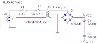
That would result in a very inefficient power supply, wasting about half of the potential. A better solution is this.

You need 2 rectifier bridges 6 A or bigger (or 8 diodes). Buy them big, they are cheap. And a big capacitor. You can use two, like in the drawing, but one bigger capacitor will do the same. Your 2 times 4700 µF are a good value to start with or 1 time 10.000 µF, choose the cheaper solution. If you can afford bigger values, go for it. It usually brings improvements in the bass.
You need 2 rectifier bridges 6 A or bigger (or 8 diodes). Buy them big, they are cheap. And a big capacitor. You can use two, like in the drawing, but one bigger capacitor will do the same. Your 2 times 4700 µF are a good value to start with or 1 time 10.000 µF, choose the cheaper solution. If you can afford bigger values, go for it. It usually brings improvements in the bass.
Thanks to pacificblue
As you had posted about heat sink 8"x4", I purchased, installed & found heating problem solved at all. Thanks again.
I read your earlier post for power supply & I am going to build my new PSU as per your design.
I going to continue this thread to ask NEW question bcoz you know my new PSU & power amp (TDA1554q).
I need buffer amp/preamp to improve my poor input signal to amplify with TDA1554q. I found some website for buffer amp / active filter but supply was 15V & you know I have 12V. If any matching buffer circuit in your mind Please Post.
Thanks & Regards.
The gain of the TDA1554 is 10. Line level should be 775 mV, which would result in 7,75 V at the output or 15 W with 4 Ohm speakers. Any normal source should be able to send the TDA into clipping.
What source do you use, that cannot deliver the 775 mV standard line level?
You don't have 12 V. The transformer has 12 V. After rectification and smoothing you get ~(1,41*12)-1,4 which is 15,5 V nominal.
You can use nearly any buffer/preamplifier with a single supply as well. You will need a virtual ground / rail splitter for single supply operation. In this article there is a section that explains how to use a single power supply on an opamp.
Thanks, you are educating me.
I understood, now I have 15,5 V Power Supply. (WOW)
As you stated TDA's output is 15Watt, & in datasheet stated 22Watt. i.e. I am doing something wrong. What should I do to get full 22Watt on 4 Ohm Speaker ?.
<WHAT SOURCE DO YOU USE > = I am using Chip DVD Player 5.1 (Six channel) <LINE LEVEL SHOULD BE 775 mV> Sorry, you know my knowedge level, i.e. 775 mV I can not tell you.
My DVD Players output has 6 Channel & accept SUB all channel sounds good. Sub sounds, but very poor. I thought, mono buffer amp may solved subs poor singal. Is that right ?
Yes, I am going to study your posted LINK.
Regards.
15 W is a theoretic value that the amplifier would deliver, if it had 15 W per channel. It only has 11 W, so a 775 mV signal with 10 times gain would drive the output into clipping.
22 W is the output you get from two channels in bridged configuration. In bridged configuration you have double the gain, so theoretically the amplifier would deliver 30 W from 775 mV input, but will not be able to do, thus clip.
CD and DVD players usually have output levels above 2 V. You will not need a preamplifier.
If all channels sound good except for the subwoofer, the problem could be the subwoofer. Could you post some information on it? Maybe it is simply too small for what you expect from it. What driver do you use? In which box? What is the crossover frequency?
I think, I using 2 x 22 W bridge.
i.e. I using Pin 1+2, 16+17 stereo input & 6&8, 10&12 for stereo
output.
I am using 8" Driver and box size is 12"x12"x12" Not using any crossover bcoz, DVD Player's sub output sends only low frequency. ( Actually this is my trial BOX incloser bcoz, it has to complete now )
In fact, I have planed for ...... (Pl. find attached picture)
Attachments
Are you aware that each driver has Thiele/Small parameters, with which you determine the right enclosure type and size?
Each driver has an efficiency, which determines, how loud it will be with a certain amount of power.
Then there is the maximum sound pressure level a speaker can achieve. That depends on its diameter, its maximum stroke and the enclosure type. The lower the frequency, the lower the maximum sound pressure you get. To give you an example Visaton's WS20E, an 8" woofer with ±3 mm stroke in a 20 l enclosure will reach ~103 dB at 100 Hz, while it will only reach ~75 dB at 20 Hz no matter, how much power you pump into it. Between 70 and 80 dB is the listening threshold of an average human at 20 Hz.
If you run it without crossover, it will sound weak, because it will add more volume to the midrange than to the bass.
My advice is
1) Find out the Thiele/Small parameters of the subwoofer driver and design the enclosure based on them.
2) Add a crossover to the subwoofer.
3) Find out the maximum stroke and determine the maximum sound pressure level you can expect.
Crossover design is not that simple. A crossover must be adapted to the drivers involved. Without knowing the speaker parameters or measurements and simulation software it will be difficult to achieve a satisfying result.
If you want to try it nevertheless, here are some links.
Speaker sim software
http://www.fesb.hr/~mateljan/arta/
http://www.speakerworkshop.com/SW/Download.htm
Active crossover project
http://sound.westhost.com/project09.htm
Active crossover simulation software
http://www.softwaredidaktik.de/filters/download.htm
Thanks for your co-operation.
Sad news is that I don't know what's wrong with me. Your posted Power Supply Unit is not working for me. At the same time my simple psu is working.
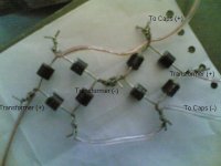
Pl. find attached picture, it is not clear but request to find whats wrong.
Thank you.
Sad news is that I don't know what's wrong with me. Your posted Power Supply Unit is not working for me. At the same time my simple psu is working.
Pl. find attached picture, it is not clear but request to find whats wrong.
Thank you.
Attachments
The only thing that can go wrong is that the diode polarities are mixed up. In the photo I cannot recognize much. Wiring and capacitors look okay, as far as I can discern. I can only recognize two diodes good enough to be sure they are the right way round. The bottom one on the right side looks, as if it were the wrong way round, but might as well be a reflection of the light. On the others I cannot recognize anything.
You should build the circuit step by step. First build one of the bridges. Check with a multimeter set to resistance across the bridges. Multimeter's COM at the connection that will later become V-. Then you measure all other connections. There should be no continuity at any time, i. e. the resistance display should always show overflow. If it does not, check the polarities and check each diode individually.
Then connect the multimeter's COM to the connection that will later be V+. Measure all other connections. You should always have continuity. If not, check the polarities and check each diode individually.
When everyting is okay, repeat the procedure for the other bridge. With both bridges tested, connect one of them to one half of the transformer secondary and check the voltage output. If you get a DC measurement, connect the other bridge to the other secondary and check the voltage output again. Then add the capacitors and check again.
- Status
- This old topic is closed. If you want to reopen this topic, contact a moderator using the "Report Post" button.
- Home
- Amplifiers
- Chip Amps
- Amp in sub encloser with fan