Hi folks,
This is sort of an introduction for me, due to my being a lurker here for more years than I care to admit, but have never chimed in until now.
I’m an audio construction addict, and my name is Mike (Hi Mike!….)
I’ve been working on a rather large scale project, off and on due to time and/or budgetary constraints, for several years. It is an integrated pre-amp, 3-way active crossover, 6-channel chip amp, with a soft-start power sequencer for silent power-up, all to drive my home brew 3-way speakers.
Here’s the problem; after testing all of the individual components for proper operation, I integrated them into a single chassis as I had originally planned, and got what seems to be a 60Hz ground loop hum that didn’t happen during the initial testing. It’s not real loud, but since I’m listening to them in the near field, it is annoying. Other than that, it works exactly as I had hoped. All of the individual components are grounded to a bus bar made from 1” X ¼” aluminum approximatly 8” long.
Now here’s the kicker; if I connect an audio source to any of the chip amps through an external volume pot it’s quiet, and then if I connect the audio source through the pre-amp section to any of the chip amps (without the external volume pot) it’s still quiet. If I connect the audio source to any of the crossover sections (for the woofer, mid, or tweeter) without using the internal pre-amp section and then to any of the chip amps (and again using the external volume pot) it’s still quiet.
However, if I have all three main sections: pre-amp, crossover, and chip amps connected in the completed unit, the hum is there. I’ve tried reconnecting all of the grounds every which-way, but it didn’t make any real difference.
I know this isn’t much to go on, but any thoughts or ideas anyone may have would be greatly appreciated. I would be happy to provide further details on the circuits and build details if necessary, and might even be able to post some pictures if that would help.
Thanks in advance,
Mike
")
Here is a link to some great info that gainfile posted.
http://www.diyaudio.com/forums/showthread.php?s=&threadid=118735
I had the same hum and after following the suggestions with wire size etc I was able to get rid of it. Hope it helps....
Yes please post some pics of your rig....
-BB
http://www.diyaudio.com/forums/showthread.php?s=&threadid=118735
I had the same hum and after following the suggestions with wire size etc I was able to get rid of it. Hope it helps....
Yes please post some pics of your rig....
-BB
OK - Here we go...
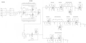
Like I said in my first post, this thing is pretty large, so I'll start with the front-end and work my way through. I'll have to take some pictures to post. Some of the scematics were made with TI's "Tina" freebee, and some will have to be scanned from my drawings. This will take some time to do, so be patient please, I’ll get it done as time permits. Also, today is Super-Hype Sunday so I’ll be busy with that. And even though I really don’t care who wins, I like watching the commercials. J
The schematic below is the pre-amp and active crossover sections, which were generated using Tina. Tina is a pretty good program, but it has some limitations that have to be worked around, such as the lack of rotary switches. What looks like a bunch of SPST switches for the input and tone controls are actually rotary switches. The input switch is a dual-deck, five position, shorting rotary switch that I already had on-hand, so that’s what I used to save some of my hard earned $’s. Because it’s a shorting switch and I didn’t want to be shorting the outputs of my program sorces to each other, I made the intermediate positions “Mute” to avoid that. It’s designed to switch the “Hot” and the “Ground” of each signal source to minimize any possible ground loops.
The tone control section has dual-deck, eleven position shorting rotary switches. The tone controls have 6dB slopes, a maximum cut or boost of 6dB in 1.2 dB steps, and have variable turnover frequency adjustments on the PC board. I’ve never liked the sound of the usual Baxandall controls with their interaction, phase shfts, and ridiculously large cut and boost ranges. This circuit offers the ability to correct minor deficiencies without totally mucking-up the sound. I chose to use rotary switches rather than pots to avoid the problems associated with the poor tracking between resistive elements, thus avoiding left-right channel differences, and to achieve virtual out-of-circuit performance at the center position.
The output section of the pre-amp is pretty ordinary other than using paralleled op amps to drive the total input impedance of the crossover filters with low distortion.
There are separate PC boards for each tone control circuit as well as the output circuits, with a total of four for stereo.
Power for the entire pre-amp section is supplied through independent left and right 317/337 voltage regulators driven from the main 36 volt power supply. Each PC board is independantly connected to the voltage regulators, with the circuit grounds going from PC board, to voltage regulator board, to the main power supply, which is integral to the bus bar ground (See photos of bottom view.)
You may notice that some of the crossover boards are missing, and not everything is connected due to my attempts to fix this ground loop issue. As I said earlier, it was all together at one time and I was very pleased with it other than that @%$#! hum.
More to follow…
Attachments
- Status
- This old topic is closed. If you want to reopen this topic, contact a moderator using the "Report Post" button.