Hi,
Could not find the exact answers to my questions in other threds, so i start one myself.
I have just finished putting together my Chipamp from ChipAmp.com, and have some questions before i start mounting in the chassis.
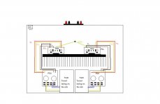
I have attached a pic of how i want to place things in the chassis, does the layout seem reasonable?
Now over to the wiring, i have drawed it up as i have interpreted the manual, does it look ok?
Isn't there gone be a ground issue with two transformers in one chassis?
Could not find the exact answers to my questions in other threds, so i start one myself.
I have just finished putting together my Chipamp from ChipAmp.com, and have some questions before i start mounting in the chassis.
I have attached a pic of how i want to place things in the chassis, does the layout seem reasonable?
Now over to the wiring, i have drawed it up as i have interpreted the manual, does it look ok?
Isn't there gone be a ground issue with two transformers in one chassis?
Attachments
Yes, but your adoption of isolated secondaries and twin dual rectifiers give you more options to avoid bad grounding.Nohabla said:Isn't there gone be a ground issue with two transformers in one chassis?
Don't solder your various ground connections initially. Solder on ring tags and bolt them together until you find the combination and order that gives the best performance within your system.
Separate the Signal Ground from the Power Ground in each amplifier. If the PCBs don't allow this, then choose another PCB.
However,
You must make a permanent mechanical fixing from the third protective earth wire on the mains cable to the major part of the metal chassis. No terminal strips allowed, direct connection of input wire to chassis.
Never remove this permanent connection, ever.
You can add extra nuts and washers and connections above the permanent securing nut/s.
This Safety Earth is for safety of the users/house/home/pets only.
It will cause audio degradation when building multichannel amps. Minimise the degradation, do not remove the Safety Earth, that's your challenge when you don't go the monoblock route.
AndrewT said:Yes, but your adoption of isolated secondaries and twin dual rectifiers give you more options to avoid bad grounding.
Don't solder your various ground connections initially. Solder on ring tags and bolt them together until you find the combination and order that gives the best performance within your system.
Ok, so what you are saying is that AC side of the rectifier PCB's is ok, but i need to "experiment" with the ground layout on the DC side?
By connecting the ground as i have skeched up will form a ground loop i suppose?
Can i breake the loop by inserting resistors between star ground and Amp ground? or will that hve an influence on the sound quality?
Separate the Signal Ground from the Power Ground in each amplifier. If the PCBs don't allow this, then choose another PCB.
Not quite shure i follow here, can you try and explain a little further?
However,
You must make a permanent mechanical fixing from the third protective earth wire on the mains cable to the major part of the metal chassis. No terminal strips allowed, direct connection of input wire to chassis.
Yes, the mains ground is important, it will go to the star ground
")
Sorry for all the Noob questions.
Thanks for your reply, AndrewT
One more thing:
When you mount those toroids, be careful not to create a shorted turn with the mounting bolt and mounting brackets!
The obvious approach for example of fitting a bracket at each and and running a bit of studding down the middle would be a disaster.
BTDT.
Regards, Dan.
When you mount those toroids, be careful not to create a shorted turn with the mounting bolt and mounting brackets!
The obvious approach for example of fitting a bracket at each and and running a bit of studding down the middle would be a disaster.
BTDT.
Regards, Dan.
- Status
- This old topic is closed. If you want to reopen this topic, contact a moderator using the "Report Post" button.