454Casull said:The new boards look great. Are you planning to sell them in the future?
I just did a small order of boards for now, and won't be selling them on the website too soon. If you want to build one with the boards, let me know and I can sell you a cheap set as a beta tester.
My plan was to build one and test it, and have a few friends build and test a few also. I don't foresee any issues with the boards, I just like to be thorough.
If anyone wants a set to try out, drop me an e-mail.
I have a busy weekend, autocrossing with the wife, but will try to start a build next week. I located a heatsink in my basement today to use.
--
Brian
Hi Brian,
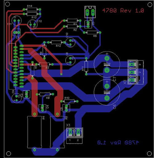
You have used split bridges for the power supply for the two different rails and then shared the current paths back to the trasformer buy usign one big plane between the capacitors.
Since you have split the rectification with two bridges, the rectifier currents will flow in a loop through the capacitor C10 and 12 for the +ve rail and C9 and C11 for the -ve rail. This means that to get the minimum rectifier noise on your star point you want to split the return paths for these two rectifiers and join them back at the connection between the two rectifiers. Then a third path should join at the rectifiers to feed the rest of the amplifer star. This way none of the rectifier currents flow in copper shared with the star point, this should reduce the ripple on the ground slightly.
Since you have already had the boards made you could try this out by cutting two slots into the ground plan to isolate a path up to the "star point" OG gnd.
This is only a minor point as you already have a good design but since you are cleary wanting to get the best out of it it may give you a slight improvement.
Regards,
Andrew
I might be interested in getting a few of those LM4780 boards for myself, but I'd be using an external PS. Would it be advantageous to use some filtering caps on the amp board too?
EDIT: I see that the board can be snapped off for just the amp. The ground trace looks mighty thin on the top, though, between C1-C6 and CHG, OG1, OG2.
EDIT: I see that the board can be snapped off for just the amp. The ground trace looks mighty thin on the top, though, between C1-C6 and CHG, OG1, OG2.
454Casull said:I might be interested in getting a few of those LM4780 boards for myself, but I'd be using an external PS. Would it be advantageous to use some filtering caps on the amp board too?
EDIT: I see that the board can be snapped off for just the amp. The ground trace looks mighty thin on the top, though, between C1-C6 and CHG, OG1, OG2.
The boards are not made to snap apart. I put a line there for a reference, should anyone decide that they would like to cut them apart. I also added the 3 pads for wiring to an external power supply.
It's better with regard to PSU and decoupling to bridge the pair of amps inside the single chip and parallel the two dual chips.
It reduces the current in each supply rail and removes much of the rail shut off that cannot be avoided with a ClassAB output stage. The rail currents approach the rail current modulation of a push pull ClassA output stage.
It reduces the current in each supply rail and removes much of the rail shut off that cannot be avoided with a ClassAB output stage. The rail currents approach the rail current modulation of a push pull ClassA output stage.
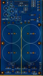
Like so?gfiandy said:Hi Brian,
You have used split bridges for the power supply for the two different rails and then shared the current paths back to the trasformer buy usign one big plane between the capacitors.
Since you have split the rectification with two bridges, the rectifier currents will flow in a loop through the capacitor C10 and 12 for the +ve rail and C9 and C11 for the -ve rail. This means that to get the minimum rectifier noise on your star point you want to split the return paths for these two rectifiers and join them back at the connection between the two rectifiers. Then a third path should join at the rectifiers to feed the rest of the amplifer star. This way none of the rectifier currents flow in copper shared with the star point, this should reduce the ripple on the ground slightly.
Since you have already had the boards made you could try this out by cutting two slots into the ground plan to isolate a path up to the "star point" OG gnd.
This is only a minor point as you already have a good design but since you are cleary wanting to get the best out of it it may give you a slight improvement.
Regards,
Andrew
Attachments
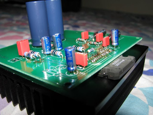
I could give that a try. I finally got around to building a new LM4780 prototype amp last night:
full size: http://www.briangt.com/gallery/lm4780r2/lm4780?full=1
ignore my lack of chassis for now")
I configured the amp in stereo configuration for this one. Will try building a pair of parallel amps next.
--
Brian
An externally hosted image should be here but it was not working when we last tested it.
full size: http://www.briangt.com/gallery/lm4780r2/lm4780?full=1
ignore my lack of chassis for now
I configured the amp in stereo configuration for this one. Will try building a pair of parallel amps next.
--
Brian
Very cool! I have been wondering...what is the difference between the LM4780 & LM3886? They seem to be the most popular chips in here, and there's the obvious difference that the the LM4780 has 2 channels. According to their datasheets, it looks like the LM4780 has the same or less THD+N at higher power outputs. Is this correct?
I plan to build a 4ch chip amp (bi-amping some 2-way's I built a while ago), as soon as the current project is done. I opted to make some nice red oak tables for the speakers to get them off my desk...then I will move on to the DIY amp part of it.
Thanks!
I plan to build a 4ch chip amp (bi-amping some 2-way's I built a while ago), as soon as the current project is done. I opted to make some nice red oak tables for the speakers to get them off my desk...then I will move on to the DIY amp part of it.
Thanks!
- Status
- This old topic is closed. If you want to reopen this topic, contact a moderator using the "Report Post" button.
- Home
- Amplifiers
- Chip Amps
- new LM4780 layout, any comments?