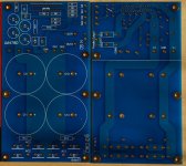
I haven't built up a LM4780 amp for a while, so I decided to make a new layout.
Goals for layout:
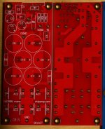
- single LM4780 + PSU on a single board
- able to be used in stereo or parallel
- reasonably compact: 3" x 5.5"
- decently robust power supply
- attempt at decent separation of grounds, allowing for a star ground for the inputs, going back to the main ground, a separate ground return for the output zobel networks and also the output grounds tied back close to the main ground.
What do you guys think?
Goals for layout:
- single LM4780 + PSU on a single board
- able to be used in stereo or parallel
- reasonably compact: 3" x 5.5"
- decently robust power supply
- attempt at decent separation of grounds, allowing for a star ground for the inputs, going back to the main ground, a separate ground return for the output zobel networks and also the output grounds tied back close to the main ground.
What do you guys think?
Attachments
BrianGT said:attempt at decent separation of grounds
Great!
Any interest in going back and doing the same for other chips? 3886?
Also, why not make it so that the board could be cut if someone wished to do so?
Re: Re: new LM4780 layout, any comments?
Here is a similar layout that I made for the LM3886, which I haven't finished fully yet.
The idea here is to have a narrow board, so that you can easily pop 2 aside each other for a dual mono amp and avoid having to wire up the power supply board to the amp board. (or to the same effect a 5 channel amp).
-Brian
toolsresearch said:
Great!
Any interest in going back and doing the same for other chips? 3886?
Also, why not make it so that the board could be cut if someone wished to do so?
Here is a similar layout that I made for the LM3886, which I haven't finished fully yet.
The idea here is to have a narrow board, so that you can easily pop 2 aside each other for a dual mono amp and avoid having to wire up the power supply board to the amp board. (or to the same effect a 5 channel amp).
-Brian
Attachments
BrianGT said:My only major concern is leaving enough clearance to attach the chip to the heatsink. I believe that with the large caps pushed back, an angled screwdriver should be able to screw the board into the heatsink.
--
Brian
On my amplifiers I placed the screws behind the heatsink and the nut + washer on the chip or transistors, so this might be an option.
Ted205 said:would be a shame to have the psu connected as the only option.")
I actually modified the design to add pads to the V+ and V- traces, in order to run it by itself, putting a cut line on the bottom of the PCB to cut the top 2" off to form just an amp board. I will post pics for this later, as I am away from that computer now.
--
Brian
Re: Re: Re: new LM4780 layout, any comments?
Don't connect it to Signal Ground (SG).
There is room to take a separate trace to the Audio Ground (AG).
What about space for RF attenuation at the input? Or do you solder the cap on the back of the PCB @ R3 location?
If you move R3 & R4 slightly right to leave space for a 330pF to 1nF cap and take SG with them, then there is room to move C6 to the other side of SG.
That then leaves the optional space for a DC blocking cap on the input. Keep three input pins SG, AC, DC, @ 0.1inch pitch.
Jumper SG & AC for testing, jumper AC & DC for bypassing the input cap, leave jumper on DC for AC coupled input. solder the input cable from the RCA to the back of SG & AC.
Remove pins 2 & 11, leaving more room for the adjacent traces.
After all this is there room to add a 10r to the trace from SG to AG?
If you saw the PCB just above R8, then add a couple of pads to the V+ & V- traces on both halves of the PCB.
There is an external report that is linked from this Forum saying that pin7 sends out a dirty current.BrianGT said:Here is a similar layout that I made for the LM3886, which I haven't finished fully yet.
Don't connect it to Signal Ground (SG).
There is room to take a separate trace to the Audio Ground (AG).
What about space for RF attenuation at the input? Or do you solder the cap on the back of the PCB @ R3 location?
If you move R3 & R4 slightly right to leave space for a 330pF to 1nF cap and take SG with them, then there is room to move C6 to the other side of SG.
That then leaves the optional space for a DC blocking cap on the input. Keep three input pins SG, AC, DC, @ 0.1inch pitch.
Jumper SG & AC for testing, jumper AC & DC for bypassing the input cap, leave jumper on DC for AC coupled input. solder the input cable from the RCA to the back of SG & AC.
Remove pins 2 & 11, leaving more room for the adjacent traces.
After all this is there room to add a 10r to the trace from SG to AG?
If you saw the PCB just above R8, then add a couple of pads to the V+ & V- traces on both halves of the PCB.
I've a few questions, out of curiosity, basically.
Why not attach the leds trough the bleeder resistors, instead of adding seperate tracks? The currnet through the bleeders is wasted anyway, might as well use it for something more. Or this is not a good idea, due to something I'm missing?
Maybe add a track for an (optional) snubber as well, for people that might want to install it.
Hi Brian,
I am not an expert by any means but I have some comments:
R9 for muting seems low at 1k, is it 10k maybe?
R10/11 snubbers seem large at 1k, I would use something around 1R
also you might want to consider putting some optional 22uf-150uf capacitors between R7/R8 and GND
although it might be against your philosophy, you could use soft-recovery bridge rectifiers instead of MUR860's.
lastly capacitors C3-C6. I know you use a similar scheme in your LM3886 kits but I think it might sound slightly brilliant. I would go for 1x or 2x 470uf / rail but probably testing is the best route.
the layout is very neat - nice one
Evan
Atilla said:Great, keep us posted, those boards are looking really nice.
Thanks! I really miss working on projects, as I have been quite busy with work and car stuff, but am really trying to put more time into building stuff. This should motivate me to get back into building stuff
- Status
- This old topic is closed. If you want to reopen this topic, contact a moderator using the "Report Post" button.
- Home
- Amplifiers
- Chip Amps
- new LM4780 layout, any comments?