Thank you to all who have helped me over the years. It has been so long since I started this project that I cannot even recall all of you, but thanks.
Motivation: 8 Channels for SoundEasy Speaker Design DF
Design Goals: Drive 4ohms ea., re-usable for HT.
Specs:
8x115W/ch rms into 4ohms
2x800VA toroid
172000uF total
Being my first amp, I learned quite a bit!

-Bob
Motivation: 8 Channels for SoundEasy Speaker Design DF
Design Goals: Drive 4ohms ea., re-usable for HT.
Specs:
8x115W/ch rms into 4ohms
2x800VA toroid
172000uF total
Being my first amp, I learned quite a bit!
-Bob
Attachments
pics
let me know how this goes -- never did it and don't know if I set permissions and have link correct. -bob
http://s576.photobucket.com/albums/ss202/rgrayton/Gargan8/
let me know how this goes -- never did it and don't know if I set permissions and have link correct. -bob
http://s576.photobucket.com/albums/ss202/rgrayton/Gargan8/

journey
Yes, I am familiar w/SE, and now I should be able to perform digital filtering – you need an amp per driver, so a 4-way spkr will require 8 ch for stereo.
Yes, Rectifier boards are 4 per toriod. On top of them is a 30ohm R to slow the I surge on pwr up – not needed with my prototype (2ch, one toroid). When I added the second toroid (or maybe that was second w/added caps), I started flipping the breaker. I did not want any more design than required, so I opted for the less elegant solution of simple slowing the current thru the input R. The relay shorts this R, once the surge is over and the R is out of the picture. There are other (better?) solutions out there, but this thing was dragging out and I needed to get it done.
I did have a hum, before I went to a star ground. Now, all 8 pcb have pretty much the same amount of copper between them and the star. I don’t think I am overstating myself when I say it was as much of a mechanical challenge as electrical one – fitting all that stuff in a single box and not looking like a rats nest.. I was too lazy to make 2 separate boxes. I really could not see any other solution than a (actually 2) huge heat sink on the box rear. Once that is defined, basically that sets the size of the box, at least in height. The toroids and caps set the size in w and d. My proto only would output about 60W/ch into 4 ohms – that was with the 2x1500uF on the pcb for the chipamp. After some direction from the board, it became apparent I needed to add much more, if I was looking for anything close to the 120W rating of the LM4780, so I added 2x10K per ch. What you wind up with is a nice power supply with a couple chips hanging off. Now, I measure about 21.5Vrms across an output load on each ch, driven w/1KHz signal. -bob
I don't believe that the capacitance is doing anything to increase the amplifiers output. It's really just a filter. It's the transformer which should be offering the continuous voltage and current necessary to drive the amps to their peak output. The capacitor filter directly after the rectifier does offer a voltage increase, but that voltage increase is limited to no more than 1.5 volts regardless of how much capacitance there is. The only way I could see the capacitors increasing output would be over sustained peaks which were previously draining the onboard caps before you took the measurement, and thus lowering the voltage.
None the less I have always agreed that the onboard capacitance wasn't even close to enough for those, and was never able to get my amplifiers to sound right with just the 1500uf's onboard. I personally changed mine out with 100uf film caps which have a much lower esr mixed with 1000uf panasonic fc's (I think thats what I did, been a while), all hooked to a CLC power supply I made from some extra parts I had from my big amp project. This uses 48,000 uf's of Hitachi brand capacitors per rail, then 11mh of inductance, followed by 96,000 uf's of capacitance. While others have argued that their is no scientific reason why such a quiet power supply is necassary, given the amps ripple rejection, besides hearing a difference in the noise floor, I can measure a difference in the noise floor, as well as distortion levels at very lower power (<1 watt), indicating reduced noise from the power supply in the output signal.
None the less I have always agreed that the onboard capacitance wasn't even close to enough for those, and was never able to get my amplifiers to sound right with just the 1500uf's onboard. I personally changed mine out with 100uf film caps which have a much lower esr mixed with 1000uf panasonic fc's (I think thats what I did, been a while), all hooked to a CLC power supply I made from some extra parts I had from my big amp project. This uses 48,000 uf's of Hitachi brand capacitors per rail, then 11mh of inductance, followed by 96,000 uf's of capacitance. While others have argued that their is no scientific reason why such a quiet power supply is necassary, given the amps ripple rejection, besides hearing a difference in the noise floor, I can measure a difference in the noise floor, as well as distortion levels at very lower power (<1 watt), indicating reduced noise from the power supply in the output signal.
pj,The only way I could see the capacitors increasing output would be over sustained peaks which were previously draining the onboard caps before you took the measurement, and thus lowering the voltage.
I think you hit the nail on the head with this statement. My test was a sustained one. 1kHz in, 4ohm load on output, dvm and scope across load. Scope showed clipping as stated: 65W and 115W, respectively to PS cap profiles. BTW, it also sounded much better, too. I am not exactly sure whether this was due to large caps or other filtering I added. My suspicion is both. Transient peaks should have been less distorted. -bg
rgrayton said:What kind of problem? PS boards in parallel, 4 per toroid.
People can debate whether a giant power supply is better or worse than many small supplies but that is not what I am talking about. Here you have a bunch of diode bridges connected to the same AC Windings on your transformer.
Just going off the the top of my head, and I could be wrong. All those diodes when conducting present a slightly different impedance which at times is very low. So I worry that one diode set (the lowest impedance) would hog all the current and no current (or very little) would flow to the others during the main charging cycle at the top/bottom of the waveform. One set would dominate and the dominant set would differ depending on load/ AC phase, etc...
You will see that they all charge up under no load but when you start using all those channels will the power supply banks be recharged when they need to be? I suspect not.
Kind of like the reason we use emitter resistors in power amps with banks of output transistors- to prevent one output transistor from dominanting.
However, I am not a circ. expert so I could be wrong. But I have never seen anyone do this kind of thing before here either...wonder if I just missed it or if there is a reason for not doing it (other than spending less $$ on diodes/bridges)? I tried to use 2 bridges with a low power transformer in a preamp and it didn't work, but again it could be just me.
Do you have any issues with your DC voltages? Does this work flawlessly?
Hi,
have you wired each 4780 to operate in parallel mode? (115W into 4r0).
What supply rail voltage does the amp operate on in the quiescent condition?
How much does this supply voltage sag when one channel is delivering maximum power?
Could you post more details of how you connected the star ground to all the amps, power supplies, etc?
What input filters (HP & LP) have you fitted to each amplifier?
Which topology did you choose? inverting, non-inverting, AC coupled, DC coupled, gain, NFB values?
Hi,pjpoes said:I don't believe that the capacitance is doing anything to increase the amplifiers output.
where does this disbelief come from?
He tells us he got 60W into 4r0 with one smoothing arrangement and 115W into 4r0 with the higher value smoothing arrangement.
What's to disbelieve?
look like
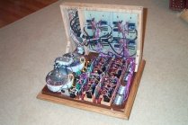
It looks like he is using the old chipamp.com 4780 boards which are parallel non-inverting.
Also hooking up 4 of their 8 diode power supply boards to each transformer such that each AC winding is connected in parallel to 4 different diode bridges (4 diodes per bridge).
It looks like he is using the old chipamp.com 4780 boards which are parallel non-inverting.
Also hooking up 4 of their 8 diode power supply boards to each transformer such that each AC winding is connected in parallel to 4 different diode bridges (4 diodes per bridge).
Neither am I a circ expert. I was driven by the need for 8 chs and know only what I need to learn to get this done. I can’t really give a further report as I have not put this thru its paces, yet. Maybe someone else with more knowledge can comment on my chances, although not personal, I hope you are not correct about my impending doom. My uninformed thinking would be that there is enough capacitance to handle any instantaneous requirements and the toroids big enough to deliver as required, but we shall see. Is long as there is enough VA available, I would think this should work and my intended use should not require high pwr to all chs at the same time.However, I am not a circ. expert so I could be wrong. But I have never seen anyone do this kind of thing before here either...wonder if I just missed it or if there is a reason for not doing it (other than spending less $$ on diodes/bridges)? I tried to use 2 bridges with a low power transformer in a preamp and it didn't work, but again it could be just me. Do you have any issues with your DC voltages? Does this work flawlessly?
have you wired each 4780 to operate in parallel mode? (115W into 4r0).
What supply rail voltage does the amp operate on in the quiescent condition?
How much does this supply voltage sag when one channel is delivering maximum power?
Yes, parallel – needed for that kind of pwr into 4ohms. Rails are 36V, quiescent. I don’t have sag numbers w/cap upgrade, but I just looked at my notes from the original testing using only the pcb caps (1500uF).Could you post more details of how you connected the star ground to all the amps, power supplies, etc? What input filters (HP & LP) have you fitted to each amplifier? Which topology did you choose? inverting, non-inverting, AC coupled, DC coupled, gain, NFB values?
8ohm load
Rail at clip: 34
V across load: 20V, 50W
4hom load
Rail at clip: 33
V across load 18V, 81W
So, let me amend my previous comment about 65W to 50 and 81, respectively. The rail really does not change all that much, it appears.
Star ground. Each PS board ground is connected to a single point, relatively close to the PS boards and symmetrically distance w/copper. Same for the chip boards to the same star.
http://cid-57e7547c65e8c675.skydrive.live.com/browse.aspx/Gargan8?authkey=HgdwYqjQmcw$&ct=photos
Not sure what you mean by input filters. Do you mean signal? Non-inverting, if I remember correctly. Basically the Brian pcb and kit. See if you can view the ckt in the above link.
Attachments
look like
Yes, correct.
It looks like he is using the old chipamp.com 4780 boards which are parallel non-inverting. Also hooking up 4 of their 8 diode power supply boards to each transformer such that each AC winding is connected in parallel to 4 different diode bridges (4 diodes per bridge).
Yes, correct.
rgrayton said:
Neither am I a circ expert. I was driven by the need for 8 chs and know only what I need to learn to get this done. I can’t really give a further report as I have not put this thru its paces, yet. Maybe someone else with more knowledge can comment on my chances, although not personal, I hope you are not correct about my impending doom. My uninformed thinking would be that there is enough capacitance to handle any instantaneous requirements and the toroids big enough to deliver as required, but we shall see. Is long as there is enough VA available, I would think this should work and my intended use should not require high pwr to all chs at the same time.
***
I think you have sufficient capacitance but the problem as I see it is that you do not deliver voltage and current to the all capacitors to charge them. So even though you have an 800VA transformer it only is able to feed one PS board at a time because one of the 4 parallel bridges conducts all (or most of) the current. I am sorry to have to point this out, but the more I think about it the more I think I am correct. (Easy fix- just use 2 large bridges per toroid and put all those caps in parallel). Andrew knows what he is doing so maybe he will comment about this?
I think Andrew is asking about how you intend to filter the input signal to the various drivers. You are not going to send a full range signal to your tweeters and midrange right?
- Status
- This old topic is closed. If you want to reopen this topic, contact a moderator using the "Report Post" button.
- Home
- Amplifiers
- Chip Amps
- 900W LM4780 Gainclone