Hello People
I want to know if i can use my Logitech Z-5300 Speakers without SoundTouch remote
i want to isolate the remote so i can use my decoder only beside using the both remotes.
in other words if one lost his remote how will he be able to use the speakers because the power button of speakers is located on the wired remote and if remote is not connected on sub we cant turn it on
i have seen Z-5500 hacked thread so may be someone can help
thanks
Hello People
I want to know if i can use my Logitech Z-5300 Speakers without SoundTouch remote
i want to isolate the remote so i can use my decoder only beside using the both remotes.
in other words if one lost his remote how will he be able to use the speakers because the power button of speakers is located on the wired remote and if remote is not connected on sub we cant turn it on
i have seen Z-5500 hacked thread so may be someone can help
thanks
Has anyone made any progress in getting the z-5300 working without the pod?
I have been able to turn on the amp by shorting pin 6 & 7 on the "vga" connector but I get no sound. If I remove the short, the amp powers off and the heatsinks go back to being cold.
It appears that I was unsuccessful in getting any sound by jumpering various combinations on the "vga" connector. So I finally unscrewed the amp assembly from main sub box and found the low level signal section of the board, located at the center region, has a ton of parts and complicated.
I decided to try a different route. There are 3 sets of wires entering/exiting the sub box and were easily identifiable by where the wires connect to on the circuit board. The three sets consist of 120volt mains to the transformer, 3 leads from secondary side of the transformer, and the speaker wires to the sub driver. Close by is the low level signal wire to the amp chip. I desoldered the wire from the low level signal section. I plugged the power cord in with "vga" connector pin 6 & 7 shorted and touched the bare wire on the signal wire to the amp with my finger. I get the familiar hum from the sub driver. So far so good. At least I can turn the z-5300 into a subwoofer.
Next I will try to add a connector to the end of the signal wire to the sub amp.
An update. I have connected the sub amp signal wire to the backside of the 3.5 mm jack (orange color) marked center/sub thus bypassing the pre-amp section . Wow! It works. Too LOUD!!! Volume control will be required to attenuate the output.
As for the other channels, I have mapped out which amp chip corresponds to which channel. Next is to pull the signal wires and connect to the backside of the 3.5 mm jacks - same as what I did for the sub amp.
As for the other channels, I have mapped out which amp chip corresponds to which channel. Next is to pull the signal wires and connect to the backside of the 3.5 mm jacks - same as what I did for the sub amp.
Success! Not quite. I found out the front left amp does not work.
I noticed the functioning front right is not as loud as rears. So I connected the rear amp audio inputs to the backside of the 3.5mm front audio input jack. I will have to re-label the output so in the future I do not get confused.
For the audio input to the amps, I removed the shielded cable and added a header. I used an unshielded computer cdrom audio cable soldered to the backside of the 3.5 mm audio input jack and the other end plugged into the header.
An update. I have now wired the center channel amp input to the back of the 3.5mm jack.
I have noticed that there is much greater hiss and buzzing from the center channel than the other working speakers (front left is dead). This happens with the inputs shorted to ground at back of amp or connected to the computer (on & off makes no difference).
Has anyone else found a greater amount of hiss or buzzing from one speaker compared to the rest???
decent sounding amp chip
Another update. I discovered the amp chips are very decent sounding. I was selling my Camber 1.0ti speakers and I needed an amp to connect to demo. I used the z-5300 connected to my Blackberry - wow! (without the sub of course). I was expecting mediocre sound but was amazed with this setup. The only issue was the speaker wire connection had to be done with an RCA audio cable and an RCA jack soldered to wires to make the final connection to the speaker.
Another update. I discovered the amp chips are very decent sounding. I was selling my Camber 1.0ti speakers and I needed an amp to connect to demo. I used the z-5300 connected to my Blackberry - wow! (without the sub of course). I was expecting mediocre sound but was amazed with this setup. The only issue was the speaker wire connection had to be done with an RCA audio cable and an RCA jack soldered to wires to make the final connection to the speaker.
Wendle
i took my z-5300 apart and studied it in view of your notes. i figured that the subwoofer input goes through a coax from the center of the board to the lower left to go into the amp.
i tried cutting the sub woofer red and black wires as it exited from the speaker part of the box and connected them to an rca connector.
i then connected my soundbar output to the subwoofer to each of the inputs with a standard 2 wire 1/8" jack.
then i took the rca connector from the internal subwoofer in the logitech and tried plugging it into each rca speaker connector.
i heard nothing.
the power supply heatsinks get warm and the output ic's get very hot.
do you suggest it try anything else or just toss it in.
thanks
Wendle
i took my z-5300 apart and studied it in view of your notes. i figured that the subwoofer input goes through a coax from the center of the board to the lower left to go into the amp.
i tried cutting the sub woofer red and black wires as it exited from the speaker part of the box and connected them to an rca connector.
i then connected my soundbar output to the subwoofer to each of the inputs with a standard 2 wire 1/8" jack.
then i took the rca connector from the internal subwoofer in the logitech and tried plugging it into each rca speaker connector.
i heard nothing.
the power supply heatsinks get warm and the output ic's get very hot.
do you suggest it try anything else or just toss it in.
thanks
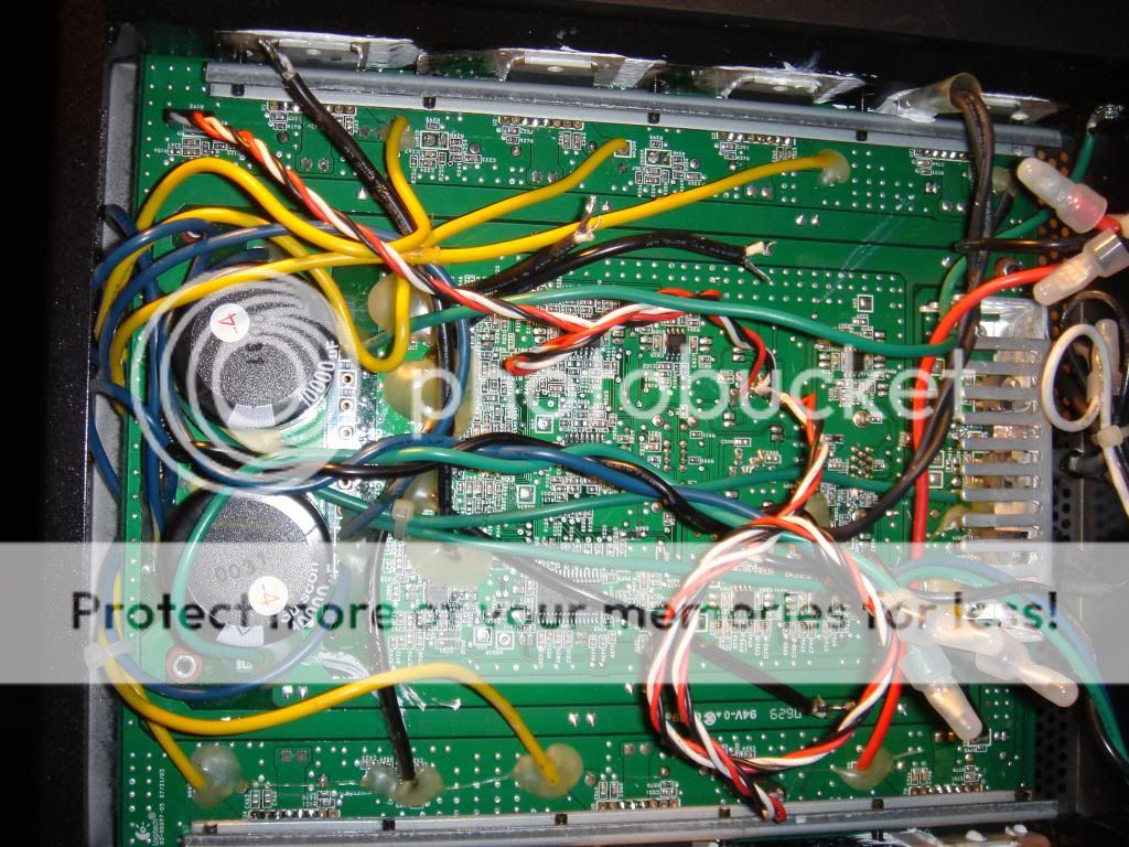
I assume you are still trying to use the internal amp for the subwoofer driver. If yes, then all you need to do is to bypass the pre-amp section and connect from the 3.5 mm jack (near center of board) direct to the input of the chip amp. IMO to use one of the RCA jacks as an input is too much work.
So what I did was disconnect the black shielded wire from the output of the pre-amp to the chip amps input then jumper from the 3.5 mm jack direct to the chip amp. In my photo these are the twisted red, white, and black wires. Note the 3.5 mm jack for subwoofer input also contains the center channel input - but easy enough to figure out.
Update 2014: remote pinouts
I have one of these boards on my desk and I took the time to study the connections to the remote control connector.
1. GND
2. Headphones 1
3. GND
4. Headphones 2
5. GND
6. +5V power to remote
7. GND
8. GND
9. GND
10. not connected (I think so)
11. STBY command from remote to system
12. MUTE command from remote to system
13. Spatial stereo command from remote to system
14. I2C SCL from remote to system (NJW1150)
15. I2C SDA from remote to system (NJW1150)
Pins 1,3,5 are analog ground. The other grounds are digital.
I don't know which Headphones signals is left and which is right.
Pins 11 and 12 go to the bases of two NPN transistors, so series limiting resistors are mandatory (10k should be fine). The bases of these two transistors are tied to +5Vcc on the system board through 20k resistors.
Tie pin 11 to GND to get the TDA power IC's out of standby. Leave open or to +5V for stand-by. The thermal sensor (normally closed connection) is connected between pin 11 and the base of the standby transistor. When overheat, it opens and the power ICs go to standby.
Tie pin 12 to GND to get the power ICs out of MUTE mode. Leave open or tie to +5V for MUTE On.
Tie pin 13 to GND to get the same effect as setting the swith on the back of the board to the "2ch" mode. In this mode, the rear channels are obtained from processing the two front channels (a sort of spatial stereo, they filter FR and FL then get the R-L and L-R signals which become the rear signals).
Pins 14 and 15 go straight to the system's volume and tone controller, NJW1150.
Its datasheet can be found on the internet, and I believe it's piece of cake to control with an Arduino.
I'm working on a small controller based on a PIC mcu (18F2550) because that's what I've got laying around.
Edit: I've just realized that the series 10K resistors are not needed because of the on-board pull-up 20k resistors. It would be best to use open-collector outputs to attack pins 11 and 12. Perhaps 13 too. Or better, use latching switches to GND.
Last edited:
Hi ceteras,
How far did you get with your hacked board?
Any chance you could take pictures of the original pcb or any one else?
I attempted to see if I could fire bits at the sdl scl lines with an arduino with no success, I will post what I tried from your pin out there tomorrow.
0x08 //mute register
0x00 //unmute 0x01 mute
I tried putting both the stby and mute to gnd and +5v didnt seem to do anything as well.
The arduino crashes when i try to send to the i2c address of 68 (0x44) so not sure whats going on there tried to swap the wires and put a 4.7kOhm pullup resistor to 5v on both sdl/scl also didnt help. Hopefully that i2c volume chip isnt bad in my subwolfer. :/
Let me know if you have any updates.
Thank you.
Last edited:
So I was unable to get a reading from the i2c Volume IC
14. I2C SCL from remote to system (NJW1150)
15. I2C SDA from remote to system (NJW1150)
So I soldered leads right to the pins of the NJW1150 Pins 16 SCL / 17 SDA
I was then able to detect the address of the NJW1150 which is (HEX 0x44) as said in the documentation (Binary 1001000) (Decimal 68).
Arduino Playground - I2cScanner
Scanning...
I2C device found at address 0x44 !
done
Here's my quick code that doesn't work for me but maybe helps someone in the future it's how I believe it should work. The code unmute's the NJW1150 waits 2 seconds, then changes the volume to max waits 2 seconds, then volume min wait 2 seconds, Repeat...
I'm not sure I even understand how to power up the board I know its on as its putting 5-6V out of pin 6 +5V power to remote.
I put both:
11. STBY command from remote to system
12. MUTE command from remote to system
to GND and no sound seems to come out.
Here is an image of the soldering from the arduino.
Blue wire goes to Pin A5 on the arduino (SCL) and white wire goes to Pin A4 (SDL).
I also have two 4.7KOhm pullup resistors to 5V on the SCL, SDL Lines.

I might put the scope on it later to see if Im actually changing anything on the NJW1150 but that's all I can muster for now.
Hope it helps!
14. I2C SCL from remote to system (NJW1150)
15. I2C SDA from remote to system (NJW1150)
So I soldered leads right to the pins of the NJW1150 Pins 16 SCL / 17 SDA
I was then able to detect the address of the NJW1150 which is (HEX 0x44) as said in the documentation (Binary 1001000) (Decimal 68).
Arduino Playground - I2cScanner
Scanning...
I2C device found at address 0x44 !
done
Here's my quick code that doesn't work for me but maybe helps someone in the future it's how I believe it should work. The code unmute's the NJW1150 waits 2 seconds, then changes the volume to max waits 2 seconds, then volume min wait 2 seconds, Repeat...
Code:
//Start Code Arduino Sketch Z-5300 SoundTouch Wired Remote Control.

#include <Wire.h>

//NonaSuomy

void setup()
{
  Wire.begin();
  Serial.begin(9600);
}

void loop()
{
  Serial.println("UNMUTE");
  Wire.beginTransmission(0x44);//(0x44) Device Address 68 Decimal
  Wire.write(0x08); //Mute Control
  Wire.write(0x00); //Unmute 0x00 Mute 0x01
  Wire.endTransmission();
  delay(2000);

  Serial.println("VOL+");
  Wire.beginTransmission(0x44);//(0x44) Device Address 68 Decimal
  Wire.write(0x00); //Master Volume
  Wire.write(0x4F); //“1001111”=-79dB
  Wire.endTransmission();
  delay(2000);

  Serial.println("VOL-");
  Wire.beginTransmission(0x44);//(0x44) Device Address 68 Decimal
  Wire.write(0x00); //Master Volume
  Wire.write(0x50); //“1010000”=MUTE:Default Value
  Wire.endTransmission();
  delay(2000);
}
//End Code Arduino Sketch Z-5300 SoundTouch Wired Remote Control.
I'm not sure I even understand how to power up the board I know its on as its putting 5-6V out of pin 6 +5V power to remote.
I put both:
11. STBY command from remote to system
12. MUTE command from remote to system
to GND and no sound seems to come out.
Here is an image of the soldering from the arduino.
Blue wire goes to Pin A5 on the arduino (SCL) and white wire goes to Pin A4 (SDL).
I also have two 4.7KOhm pullup resistors to 5V on the SCL, SDL Lines.
I might put the scope on it later to see if Im actually changing anything on the NJW1150 but that's all I can muster for now.
Hope it helps!
Cracked it! Works now was just me not understanding attenuation...
Wire.write(byte(0x00)); //Master Volume
Wire.write(byte(0x00)); //“0000000”=0dB (Full Volume-ish)
Also I soldered my pins backwards on my VGA header as to why I couldn't power on the AMP once I figured out that I finally heard a pop from the sub powering up when I grounded both STBY and MUTE, but not sure if I can still get an i2c connection from the back VGA header will try after I get some better code for dealing with the options of the chip.
So ecstatic right now!
I'll see if I can make a silly remote for fun, will share if I figure anything else out as if it wasn't for ceteras PIN OUT I probably would have thought it was impossible as I was finding no information on this unit besides people asking about replacements and NO the Z-5500 does not use I2C, the Z-5200 uses I2C.
I'll paste some brain dumps I was doing later I used a VGA port off an older video card that was detachable (header pins) as it has HDMI and DVI on the card.
Interested in results!
Hi! New user here with the same system as you have described here.
I, oddly have found a few things myself. But first a little background:
I acquired the z5300e system quite a while ago from a friend as a gift and I've recently started to "finish" my garage. As part of this job, I thought it'd be neat to wire the garage for surround sound, so using the 5300, I set to it.
Using RCA extensions, VGA extenders, wall plates, and a lot of sweat and time cramped in the attic, I finally finished wiring the entire system to place each speaker in its respective corner/center while creating a shelf for the subwoofer above the garage door. I intended to place the control pod near the entry to the house so I could power on the system when I enter the garage, and turn it off when I go back inside.
After doing all of this, and failing to power the control pod at the extended distance I started doing some research and found (like many have already) that VGA extenders cannot be used to extend the pot further from the subwoofer enclosure. That's damn annoying, but I figured I'd still attempt further.
In a funny set of circumstances (and ordering the wrong cabling) I picked up a gender changer I needed to connect the system. Here's a simple schematic of what I have going on:
Logitech z5300e-->F/F Gender changer--->M/M 1.5' VGA extension cable--->wall plate(F/F VGA coupler)--->50' M/M VGA cable--->wall plate(F/F VGA coupler)---->M/M Gender changer---->Control pod
So first off, yes I realize I have quite a few unnecessary joints in there (specifically the gender changers) but I wasn't very attentive when ordering the parts.....
Next, I thought I'd share some findings. In realizing my error, I had to make several (separate) purchases of equipment to complete my design. So, initially, to test everything (without the extension leg) I affixed the control pod to the sub enclosure above the garage door and cranked the volume to maximum. With my iPhone connected to the stereo jack (green) I adjusted the sub output until it fit my liking.
Once I received all of the necessary gender changers, I wired the system according to my design (above) and found that the system worked as I had designed with one exception. I had zero control with the pod. No lights, no power, nothing. This isn't the worst possible thing that happened actually because with the volume maxed out initially, I could control all of the sound with my iPod, albeit the control was linear. I didn't have subwoofer control, fade, or center control. Annoyed, I figured I'd just leave the control pod plugged in it's original spot above the garage door, and if I ever needed to adjust it, I'd have to close the garage door, get on a ladder, and make my adjustments....
However, I was still quite confused why the system worked *as if* the control pod was connected, yet didn't do execute any of the control features. So after some troubleshooting I found that the gender changer that I had connected to the VGA port on the subwoofer enclosure must have something to do with it. My theory is, that since the gender changer is simply a coupler (of sorts) it doesn't have an effect on the pinouts of the circuitry. The standard VGA cables I have though must (and my research indicates that they are the reason that it doesn't work) directly effect the dysfunction of the system.
This brings me to my final point and question. Is there something I can add, or remove from the VGA cabling to extend the control to the pod (in this case over 40' away)? I have yet to fully test the output/input of each lead. I am aware that there are several schematics of this diagram available on the net, but they are for the 5500 system :-(. I may just need to resort to taking apart the control pod cabling and mirroring it via the VGA cabling I already have routed in the sheetrock :-(.
That doesn't sound fun...
I know that the thread is specifically about running this system without the control pod, but I thought the bit regarding the gender changer connected could possibly help too!
I wish there was a way to bypass everything for each channel except for the amps.
I have a 6 channel output on my computer sound card.
But bypassing the remote is also a very good thing.
Hi Jimmy154,
If you read my posts in this thread I have bypassed remote and feeding direct from my sound card. The computer is doing all the volume for separate channels and crossover for speakers and subwoofer.
@Wendle I am only seeing two connections going from the preamp to the amplifiers. What is the third wire for and do you have more pictures or a better picture of what the wires are actually soldered to.
I also don't know where to connect anything.
I don't think we are that technically advanced.
Hi, sorry for bringing up this thread again. I've got a z-5300 and it was working perfectly until a few days ago, long history short... the transformer went away. I'd like to repair it, but I haven't found a way to open the subwoofer and I don't want to break it just to see the transformer values, I can't test the output voltages because it's shorted.
Would you be so kind to tell me the voltages of the green-black-blue wires? That way I'd be able to find a replacement and attach it on the back of the amp.
Thank you very much in advance.
Would you be so kind to tell me the voltages of the green-black-blue wires? That way I'd be able to find a replacement and attach it on the back of the amp.
Thank you very much in advance.
- Home
- Amplifiers
- Chip Amps
- Logitech Z-5300 without remote