hi all,
this is my first post here but i have been a lurker for years.
i am putting together a stereo LM3875 chipamp with parts from audiosector.com. Peter, your 'building instructions' thread has been very helpful - thank you - but I am having some problems in the home stretch.
Any help would be GREATLY appreciated - this is my second swipe at putting one of these together and am getting pretty frustrated with myself. please just understand that i am pretty clueless and really just understand things like 'measure X between a and b' or 'solder Y between j and k'). I have successfully put together a Bottlehead Foreplay and a Hagerman Bugle but those are kind of fool proof (apparently") ).
).
So, I put my chip amp together and measurements look pretty good up until I check the DC offset of the speakers. These measurements seem way off from what I should expect. I couldn't resist and hooked up some cruddy speakers and a CD player - just static in the left speaker and static and faint music in the right.
here are some pics: http://www.freshoj.com/diy/chip_amp/
and here are the measurements I get with my cheapo DMM:
mains 124.6 V AC
ac1 28.25 V AC
ac2 28.45 V AC
PG-/V- 34.88 V DC
PG+/V+ 37.1 V DC
left speaker 6.5 mV DC
right speaker 13.1 mV DC
I am hoping that someone can take a look at my pics and voltages and maybe something will jump out at them? I don't have any way to generate an input signal (except a preamp )
many thanks!
john
this is my first post here but i have been a lurker for years.
i am putting together a stereo LM3875 chipamp with parts from audiosector.com. Peter, your 'building instructions' thread has been very helpful - thank you - but I am having some problems in the home stretch.
Any help would be GREATLY appreciated - this is my second swipe at putting one of these together and am getting pretty frustrated with myself. please just understand that i am pretty clueless and really just understand things like 'measure X between a and b' or 'solder Y between j and k'). I have successfully put together a Bottlehead Foreplay and a Hagerman Bugle but those are kind of fool proof (apparently
). So, I put my chip amp together and measurements look pretty good up until I check the DC offset of the speakers. These measurements seem way off from what I should expect. I couldn't resist and hooked up some cruddy speakers and a CD player - just static in the left speaker and static and faint music in the right.
here are some pics: http://www.freshoj.com/diy/chip_amp/
and here are the measurements I get with my cheapo DMM:
mains 124.6 V AC
ac1 28.25 V AC
ac2 28.45 V AC
PG-/V- 34.88 V DC
PG+/V+ 37.1 V DC
left speaker 6.5 mV DC
right speaker 13.1 mV DC
I am hoping that someone can take a look at my pics and voltages and maybe something will jump out at them? I don't have any way to generate an input signal (except a preamp
)many thanks!
john
This may not be totally related, but I can't see that the wiring is laid out with some care - twisting the power leads and using thicker wires for high current wires would be a start. For this PCB you should run wire pairs for the power and respective grounds together, twisting them to control common-mode noise.
Also, are the RCA jacks insulated from the chassis? Can't see very clearly in your pics but it seems like the signal ground is shorted out to chassis at the jack. You need to isolate them, so the ground tab on the RCA should be on the nut side of the jack, not the chassis side. It's OK to use the tab for signal ground, AFAIK.
Lastly, since you're running wires so close to each other, shielded wire for the input cable would be a good idea too.
awesome, thanks so much guys. you were both right - both my RCA jacks and speaker jacks were not insulated from the chassis. believe it or not, i deliberated a while on how to wire those up and attach them to the chassis but this is one of those steps that folks with a clue probably take for granted so i couldn't find 'jacks for dummies' info anywhere. i remember being frustrated that the jacks didn't come with instructions.
the RCA -> star ground seems to have been something i picked up on my first pass at building the amp about a year ago (before finding Peter's 'how to' thread). i almost removed it when reading Peter's thread, but as the SG was already shorted to my chassis, i figured it couldn't hurt. ha.
so after fixing the RCA jacks and bypassing my un-isolated speaker jacks i get music from the right channel. honest to goodness non-staticy music. yay! (the left channel seems to be dead. i can do some diagnosis on that and hopefully find the problem.)
so, now that you know the kind of guy you are dealing with, maybe you can help me figure out how to isolate the speaker jacks. the RCA jacks came with plastic washers that i was using incorrectly (though I am still a little surprised that everything is truly isolated as the jacks physically touch the chassis?), but the speaker jacks are kind of simpler and it seems like the simple act of sticking them through the hole in the chassis would ground them? how *should* i attach these to the chassis to keep them isolated?
oh, and yes sangram, my wiring is pretty poor. i do hope to clean it up some and Peter's thread has given me some good ideas for what wire to use where.
thanks again, you guys rock.
best,
john
the RCA -> star ground seems to have been something i picked up on my first pass at building the amp about a year ago (before finding Peter's 'how to' thread). i almost removed it when reading Peter's thread, but as the SG was already shorted to my chassis, i figured it couldn't hurt. ha.
so after fixing the RCA jacks and bypassing my un-isolated speaker jacks i get music from the right channel. honest to goodness non-staticy music. yay! (the left channel seems to be dead. i can do some diagnosis on that and hopefully find the problem.)
so, now that you know the kind of guy you are dealing with, maybe you can help me figure out how to isolate the speaker jacks. the RCA jacks came with plastic washers that i was using incorrectly (though I am still a little surprised that everything is truly isolated as the jacks physically touch the chassis?), but the speaker jacks are kind of simpler and it seems like the simple act of sticking them through the hole in the chassis would ground them? how *should* i attach these to the chassis to keep them isolated?
oh, and yes sangram, my wiring is pretty poor.
i do hope to clean it up some and Peter's thread has given me some good ideas for what wire to use where.thanks again, you guys rock.
best,
john
Attachments

The simplest way to see if the chip is OK is to check DC offset. If it shows 0V DC, it's certainly no good
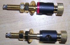
Usually, binding posts have washers and one of them comes with a lip that goes inside chassis opening. If you don't have those, use any plastic washers of apropriate size and some masking tape to isolate binding post from chassis walls.
Usually, binding posts have washers and one of them comes with a lip that goes inside chassis opening. If you don't have those, use any plastic washers of apropriate size and some masking tape to isolate binding post from chassis walls.
thanks everyone for the help - the amp is working and i am really pleased with the results.
still some 'todo's for when i have some time:
- replace the jury rigged 'insulated' jacks
- upgrade the wiring where appropriate
- clean up the routing and organization of the wiring
but for now, i am just so happy to have a working amp.
best best,
john
still some 'todo's for when i have some time:
- replace the jury rigged 'insulated' jacks
- upgrade the wiring where appropriate
- clean up the routing and organization of the wiring
but for now, i am just so happy to have a working amp.
best best,
john

- Status
- This old topic is closed. If you want to reopen this topic, contact a moderator using the "Report Post" button.
- Home
- Amplifiers
- Chip Amps
- building AudioSector chip amp - help needed