From what I have read over the last couple of weeks on this forum, I beilieve there is the potential for some hum problems with that 'paralleled' set-up and that you should ideally use one board per transformer (so two boards = two mains transformers, i.e. dual-mono).
Try Peter's specific thread... Gainclone Kit
HTH.
Try Peter's specific thread... Gainclone Kit
HTH.
Hi,
project04 directly connects both Audio Grounds to Power Ground. This will give rise to excessive hum and buzz with multi-channel amplifiers with many setups/interconnects.
The dual rectifier gives the option to keep each channel's Audio Ground separate from all others. The down side is that a disconnecting network is required for every channel to take fault current back to Safety Earth.
Monoblock outperforms all others in my experience.
could you define what "your" Audio GND is?col said:Iv'e used the ESP project4 setup with several amps I have built ............................. the audio GND doesn't go to power GND.
I think you should pretty much be able to see all the connections here:
http://pix.minirig.org.au/main.php?g2_itemId=267&g2_imageViewsIndex=1
I think my "audio GND" is the - terminal of the speaker :0
Is yours the GND of the amp module?
Haven't had any bad hums though.
col.
http://pix.minirig.org.au/main.php?g2_itemId=267&g2_imageViewsIndex=1
I think my "audio GND" is the - terminal of the speaker :0
Is yours the GND of the amp module?
Haven't had any bad hums though.
col.
Maybe because the Hypex amps have balanced inputs and the signal GND doesn't touch the case GND the project4 dual rectifier setup works?
http://pix.minirig.org.au/main.php?g2_itemId=234&g2_imageViewsIndex=1
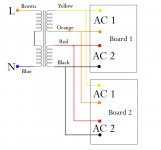
The black wires that are the centre tap are the module GND, this connects to the case GND/earth.
I don't think they do, they seem all separate, unless it takes place inside the PCB.
col.
http://pix.minirig.org.au/main.php?g2_itemId=234&g2_imageViewsIndex=1
The black wires that are the centre tap are the module GND, this connects to the case GND/earth.
How do Signal GND and Speaker GND and PCB GND connect?
I don't think they do, they seem all separate, unless it takes place inside the PCB.
col.
they must be referenced to each other and for safety must tie in to the Safety Earth.col said:I don't think they do, they seem all separate, unless it takes place inside the PCB.
All exposed conductive parts must be connected to Safety Earth. And that includes the return on the other end of the interconnect supplying signal to the power amp.
they must be referenced to each other and for safety must tie in to the Safety Earth. All exposed conductive parts must be connected to Safety Earth. And that includes the return on the other end of the interconnect supplying signal to the power amp.
opps, sorry yes they are. few too many beers last night.
I'm in the process of building a stereo amp with a pair of UcD400's, a single trafo and dual rectifiers at the moment. I had read that it is better to use 1 rectifier per rail so I tried doing this:
http://www.tnt-audio.com/jpg/psu4.jpg
but something was wrong and it kept blowing fuses, so I have defaulted back to the ESP project 4 wiring.
col.
Hi,
F1, the mains fuse, is it on the Neutral? It must be on the Live line.
The other two fuses on the secondaries are before the smoothing caps. They have to be so big to survive switch on that they provide virtually no protection in event of a downstream fault.
They must be fitted after the smoothing caps.
Size them somewhere around 1/2 the rms to peak current the amp can supply to it's rated resistive load. i.e. use F3A for a <=140W into 8r0 or <=70W into 4r0. But you may find that double this power is available from these fuses and still not suffer from nuisance blowing.
I'm going to have a go at following Nuuk's Howto:
http://myweb.tiscali.co.uk/nuukspot/decdun/gainclone_psu.html
It should be pretty much the same for a pair of UcD400s as any other module that uses power rails.
Today, Iv'e made up one of the bulb test leads and I have finished off all the metal working. Tomorrow will be wiring and testing. Will post some photos of the finished amp I hope
col.
The light bulb tester worked a treat!
In the end I stuck with the ESP project 04 wiring, mainly because of the way I laid out the components in the case. Next time I will do a rectifier per rail setup.
http://minirig.org.au/2008/12/22/minirig-hypex-ucd400/
cheers,
col.
In the end I stuck with the ESP project 04 wiring, mainly because of the way I laid out the components in the case. Next time I will do a rectifier per rail setup.
http://minirig.org.au/2008/12/22/minirig-hypex-ucd400/
cheers,
col.
- Status
- This old topic is closed. If you want to reopen this topic, contact a moderator using the "Report Post" button.
- Home
- Amplifiers
- Chip Amps
- Two rectifiers