Hmmm. If I have twin secondaries , each rated at 24V, but connect them to a single rectifier, what would be the voltage coming out of the rectifier? And if I connect the single rectifier to two separate PCB's (each with one chip attached to it), what would be the rail voltage on each PCB?
~22,6 V until you connect the necesary smoothing capacitors. With the capacitors you will get nominal 32,5 V rails. At no load the actual voltage will be higher due to transformer regulation. At full load it will be lower due to transformer regulation and capacitor discharging. And mains tolerances will also show on the secondaries.westers151 said:Hmmm. If I have twin secondaries , each rated at 24V, but connect them to a single rectifier, what would be the voltage coming out of the rectifier?
You will have to calculate the heatsink again with 32,5 V rails and with a 25 % safety margin on top for transformer regulation and mains tolerance. With the resulting 40,6 V you will not be able to run 4 Ohm speakers, and you will need the unisolated package. The heatsink should probably have less than 0,45 K/W or be supported by fans.
You need to connect both rails to both PCBs. These amplifiers need a split power supply.westers151 said:And if I connect the single rectifier to two separate PCB's (each with one chip attached to it), what would be the rail voltage on each PCB?
Heatsink caveat: With the amplifier, a decrease in voltage may or may not result in an expected amount for decrease of heat output. There are other factors, such as workload, and power supply that may have more effect than voltage variance. Aim for worst case. A minimal figure that works in practice is 0.8C/W for a gainclone stereo pair. And, personally, I would use a larger size heatsink than that.
Its not a crime to make the heatsink too big.
Expensive? Not so much. The "heat spreader" technique can be used, whereby the heatsink gets larger when it is bolted to something else, as seen here: http://diyaudioprojects.com/Chip/Synergy-LM3875-Gainclone/ when a modest heatsink is bolted to a large metal object.
Personally, I would have added ventilation holes to increase the airflow, and used $3 worth of heatsinks (as heat spreaders), making that huge pan do most of the work.
See also www.audiosector.com for some truly elegant illustrations of heat spreader technique.
westers151 said:And if I connect the . . . rectifier to two separate PCB's (each with one chip attached to it), what would be the rail voltage on each PCB? [/B]
The voltage is the same on each output.
The layout is the same on each output.
The concept isn't much different than this thing (multi-outlet):
An externally hosted image should be here but it was not working when we last tested it.
A means to hook up more than one device to a given power source.
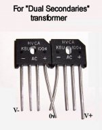
westers151 said:Hmmm. If I have twin secondaries, each rated at 24V, but connect them to a single rectifier. . . ?
Twin secondaries, connected to a single rectifier unit?
You have re-invented the center-tap transformer if your connection results in 3 lead wires like 24, 0, 24. EDIT: The secondaries are connected in series to create a center tap.
Using twin rectifiers instead:
Why not use twin rectifiers for better regulation and less voltage fluctuations? Using twin rectifiers is actually easy, because its not remarkably different than this thing (2 cell flashlight):
An externally hosted image should be here but it was not working when we last tested it.
Centerpoint in-between the 2 batteries is equal and opposing force, thus the 0v tap. That power supply is +1.5, 0v, -1.5.
A twin rectifier power supply (with caps) is the same.
I hope that puts some light on the subject.
")
Attachments
AndrewT said:as an example I have a 3886 running on +-21.5Vdc at the moment driving an 8ohm speaker.
Ta=18degC (underfloor heating)
Tsink is too hot to be comfortable.
Tc burns within about 3seconds. I'm guessing it's about 55degC to 60degC.
But the National design table says a 11C/W sink is OK when ambient is 25degC and the T version is directly connected to the sink.
The Overture Design Guide recommends 8,78 K/W for that configuration, so your 8,6 K/W are quite close.
The Guide however only takes into account that the IC must be protected, as does the table in the datasheet. It does not consider that you must not burn your fingers. The 8,78 K/W heatsink would be 120 °C hot on worst case conditions. 2,5 K/W should be the maximum for 60 °C heatsink temperature worst case, if you also account for a summer day with maybe 30 °C.
AndrewT said:I wonder how far the SPIKE trigger points have been temperature de-rated to account for the unnecessarily high case and junction temperatures?
AN-1192 tells the following.
LM3886T
Pdmax @ 25 °C = 125 W
Pdmax @ 150 °C = 39,7 W
LM3886TF
Pdmax @ 150 °C = 31 W
LM3876T
Pdmax @ 150 °C = 31 W
This last one is interesting, isn't it? The same package as the LM3886T, but Pdmax like the LM3886TF. The same figure should be valid for the LM3875.
Regards
David
Light bulb moment, but also a basic misunderstanding on my part.
I've been reading Peter's gainclone building thread and hadn't understood what he meant by using one rectifier unit shared between both chip amps. Now I do.
As for heat spreading, etc, I've seen how Peter does his cooling methods (and like the block of copper approach), but was trying to understand the basics of heatsinking before moving on to how the copper spreader connected to the aluminium chasis compares to the use of purpose built heatsinks.
Perhaps a question for Peter on his thread.
Thanks - I'm getting there slowly.
westers151 said:Light bulb moment, but also a basic misunderstanding on my part.
I've been reading Peter's gainclone building thread and hadn't understood what he meant by using one rectifier unit shared between both chip amps. Now I do.
As for heat spreading, etc, I've seen how Peter does his cooling methods (and like the block of copper approach), but was trying to understand the basics of heatsinking before moving on to how the copper spreader connected to the aluminium chasis compares to the use of purpose built heatsinks.
Perhaps a question for Peter on his thread.
Thanks - I'm getting there slowly.
Oh, I'm glad that shed some light on it.
Heat spreading can be done by attaching the chip (small size thermal interface) to a modest commercial heatsink (medium size thermal interface) and then attaching the heatsink to the aluminum chassis (large size thermal interface). That's "heat spreader" technique, and it reduces the price of heatsinks. Observe this progression from small to large, and you'll see that the whole thing is a heatsink.
Unfortunately, some people also create an oven, and we need to avoid having electrolytic capacitors in an oven. Ventilation in the enclosure is important because there's hot air in there. So, its important to allow cool air to enter at the bottom and hot air to exit at the top. When "heat goes up" this makes a nonstop breeze. That breeze extends the lifespan of the capacitors.
- Status
- This old topic is closed. If you want to reopen this topic, contact a moderator using the "Report Post" button.
- Home
- Amplifiers
- Chip Amps
- Hello and some Questions.