madisonears said:......
One thing I have noticed while testing my boards, without power, is that some measured resistance values move upward in "steps" to the correct value on the amp that works, but read the correct value immediately on the amp that doesn't work. Does that signify anything to those who know their stuff?
.......
Peace,
Tom E
If you are measuring resistance with the component "in circuit" the resistance will change / step as the connected capacitors in the circuit charge.
If you do not have that variability it either means the cap is charged fully to the potential of the meter battery or the cap is basically "out of the circuit" which would be a problem.
one channel not working
Hi AndrewT, Thanks for your help.
Here is a sketch and the voltage readings with the amplifier boards disconnected from the transformers
Blair
AndrewT said:Hi Bhm,
remove the amplifiers from the PSUs.
check the voltages again.
This time measure both the DC voltage and the AC voltage.
and tell us all the readings.
Hi AndrewT, Thanks for your help.
Here is a sketch and the voltage readings with the amplifier boards disconnected from the transformers
Blair
Attachments
Troy and Stu,
Thanks for your response, guys. Yeah, that's what I thought was happening--the caps are charging (or not) in circuit with the resistors I'm measuring. So this might be a clue as to what is wrong with one amp. Does the "non-stepping" indicate that power is going directly to ground somewhere, rather than into the caps? I've checked all the caps and they seem okay, so I don't suspect any shorts there. I simply cannot see or figure out where the short circuit might be. What would be a good way to determine if I've shorted signal or power to ground somewhere and locate it?
I will discharge all caps and try measuring resistances again.
To all: does anyone have a spare board they'd like to sell? If I cannot figure out what's wrong, I'm willing to build yet another amp, but I'd sure like to start with a fresh board. Obviously, I've screwed this one up.
Peace,
Tom E
I got my Channel to work
I wanted to report that I got my bad channel to work. Whilst I was trying to figure out how to follow AndrewT's suggestion of separating the power supply after the smoothing capacitors from the rest of the amp, I noticed that I had installed one of the zener diodes (ZD1) with the wrong orientation. Once I turned it around the correct way both channels began to work.
Thanks very much for your help and sorry to bother everyone with such a knucklehead type of problem.
Regards,
Blair
Re: I got my Channel to work
NOT a knucklehead problem, just a simple mistake. They happen and it is a PITA to find them. I am happy you found it, and you did it on your own!
Cheers!
bhm said:I wanted to report that I got my bad channel to work. Whilst I was trying to figure out how to follow AndrewT's suggestion of separating the power supply after the smoothing capacitors from the rest of the amp, I noticed that I had installed one of the zener diodes (ZD1) with the wrong orientation. Once I turned it around the correct way both channels began to work.
Thanks very much for your help and sorry to bother everyone with such a knucklehead type of problem.
Regards,
Blair
NOT a knucklehead problem, just a simple mistake. They happen and it is a PITA to find them. I am happy you found it, and you did it on your own!
Cheers!
madisonears said:Troy and Stu,
Thanks for your response, guys. Yeah, that's what I thought was happening--the caps are charging (or not) in circuit with the resistors I'm measuring. So this might be a clue as to what is wrong with one amp. Does the "non-stepping" indicate that power is going directly to ground somewhere, rather than into the caps? I've checked all the caps and they seem okay, so I don't suspect any shorts there. I simply cannot see or figure out where the short circuit might be. What would be a good way to determine if I've shorted signal or power to ground somewhere and locate it?
I will discharge all caps and try measuring resistances again.
To all: does anyone have a spare board they'd like to sell? If I cannot figure out what's wrong, I'm willing to build yet another amp, but I'd sure like to start with a fresh board. Obviously, I've screwed this one up.
Peace,
Tom E
If you post detailed pics I will look at each component for proper value and orientation.
You may also send them to me to check out against my working set. You pay shipping both ways and the troubleshooting is free. <Because it is NOT guaranteed!!
 >
>anyone got an extra LM3886?
so my 'workbench' is my floor, and I wasn't paying attention and stepped on my amp while working on it and bent the LM3886 all the way flat . IDIOT, I know. Feel free to point and laugh. It might have been ok still, but with the leads as stretched out as the were I didn't wanna take any chances and fry something else on the board, so I'm replacing the LM3886. I'm gonna be making a mouser order soon, but they don't carry the LM3886 and I don't wanna pay $7 shipping on a digikey order for one $7 part. So anyone got an extra one they could send me? of course I'll pay you for the part and for postage. email me at kevin.gentsch@gmail.com if you can help. Thanks
so my 'workbench' is my floor, and I wasn't paying attention and stepped on my amp while working on it and bent the LM3886 all the way flat
. IDIOT, I know. Feel free to point and laugh. It might have been ok still, but with the leads as stretched out as the were I didn't wanna take any chances and fry something else on the board, so I'm replacing the LM3886. I'm gonna be making a mouser order soon, but they don't carry the LM3886 and I don't wanna pay $7 shipping on a digikey order for one $7 part. So anyone got an extra one they could send me? of course I'll pay you for the part and for postage. email me at kevin.gentsch@gmail.com if you can help. ThanksAnother one lives!
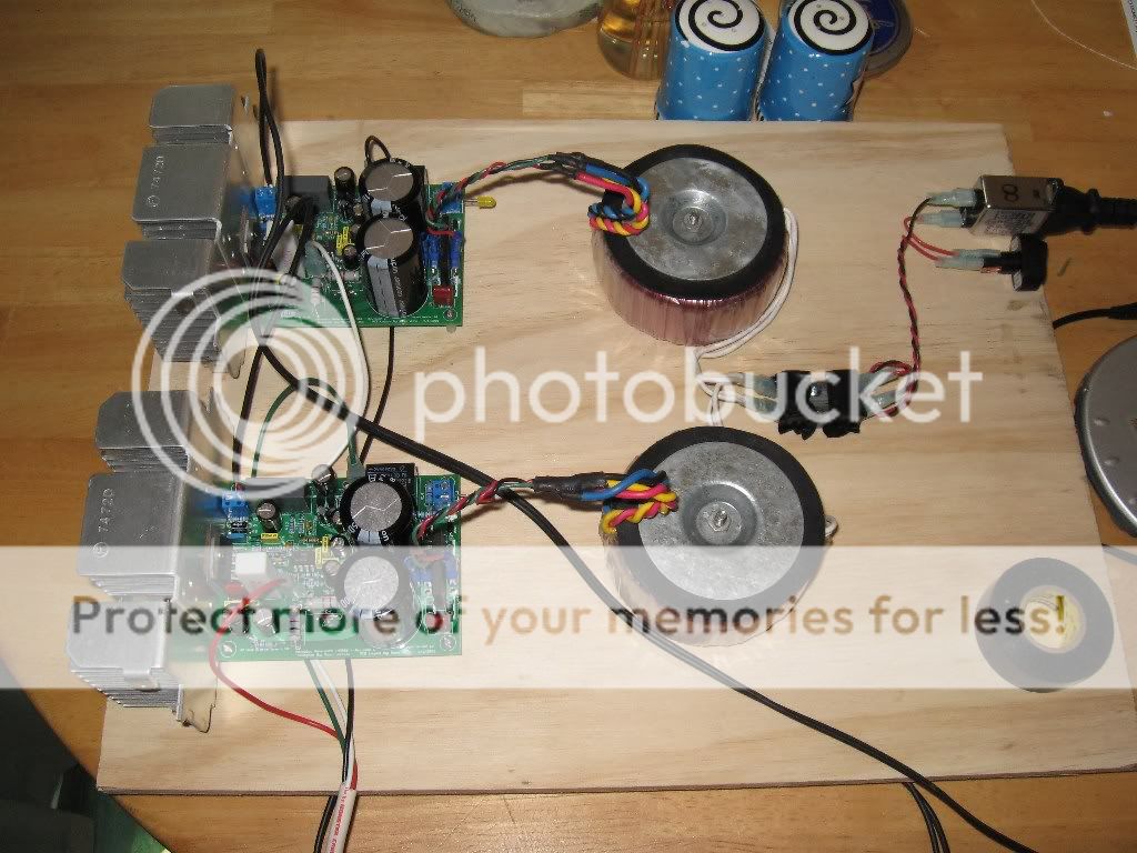
After much procrastination and letting normal life get in the way I sat down to finish it up yesterday and I am listening to it as I type this! It sounds swell too. Still need to case it up, that was one of the things I was letting get in my way of completing it, so I decided to get a nice piece of plywood an mounted everything up on that. Looks pretty good too.
After much procrastination and letting normal life get in the way I sat down to finish it up yesterday and I am listening to it as I type this! It sounds swell too. Still need to case it up, that was one of the things I was letting get in my way of completing it, so I decided to get a nice piece of plywood an mounted everything up on that. Looks pretty good too.
True I am slow... But I must have done something right, it worked first time! Sounds great for sure, can't wait to get in burned in and moved into it's new home. I am on my deck listening to it with my cj pv-7, through my outdoor speakers, even with them, though.... Nice!!
Yeah it's good to be back around.
Austin, sorry to say it is just a tad outa my way. Hope it goes great and that things are well with you and yours. Settled by now I hope.
Yeah it's good to be back around.
Austin, sorry to say it is just a tad outa my way. Hope it goes great and that things are well with you and yours. Settled by now I hope.
I'm slower......!!
Just enjoying stuffing these boards now!
I've got the resistors in, and am now considering the caps. I'll socket C9, 13, and 21 for some later tweaking, and also the LM318 (for easy replacement, unless socketing it is not recommended). Just a thought - I have some MUR860s knocking around. Do these merely replace D2-4 and the D2-4 positions are linked? Finally, I have a 1KVA trafo with dual 18V secondaries. Apart from being good for low impedance speakers (which mine aren't) is the downside just reduced power output?
Thanks for your thoughts, folks!
Cheers
Jon
Hi,
your 1kVA 18+18Vac transformer will have at least two wires forming each secondary. It may be tri-fillar or even quad-fillar.
Open up the insulation around the secondary leadouts and examine the joint where the output flexible meets the solid core windings.
You can split these multi-fillar windings and series connect them instead of parallel connecting.
This will give an option for 18, 36, and maybe 54Vac windings.
It is unusual to use wire larger than 1.6mm diameter in these small to medium size transformers. That limits each winding to about 6A.
Your 27A transformer is very likely to have quad-fillar windings. You could even get 36+36+36+36Vac from it, to independently drive a two channel amplifier. 120W+120W into 8ohms, or 220W+220W into 4ohms, or 300W+300W into 3ohms.
Re: I'm slower......!!
Hi jon,
sure you can use mur 860
jonclancy said:[B Just a thought - I have some MUR860s knocking around. Do these merely replace D2-4 and the D2-4 positions are linked?[/B]
Hi jon,
sure you can use mur 860
Attachments
- Home
- Amplifiers
- Chip Amps
- The new "My Ref" Rev C thread