If you want to achieve drastic improvements to the sound, there are lots of components in this amp that will probably provide far more payback than changing resistors. If you've already done that, then I would suggest the resistors directly in the signal path or critical to it. I think R3, 10, 12, and 13 would make the most difference. You're absolutely correct saying that some will be very difficult to replace due to proximity to other taller components, but at least resistors aren't terribly sensitive to rough handling and heat.
Because I can't seem to fix one of my monoblocks, I am in the process or building a new monoblock from scratch, incorporating all of the improvements I've made so far, and then going past that to include mostly PRP resistors and a Caddock in place of the cement Xicon. I plan to compare that monoblock to the one that still works to see if "better" resistors offer any additional improvement.
By the way, the broken monoblock puts out a low level hum and one volt (yes, one volt) of DC on top of the music signal. I actually played it for a while, but I figured it's not doing my speakers any good. Didn't seem to harm them at all, though, at the time.
So instead, I'm listening to a spare amp, a Simaudio Celeste with about 85/channel. It's a decent amp, but it sounds awful compared to the My Ref. I am already thoroughly spoiled.
Peace,
Tom E
As I said from the begining, Mauro did an excellent job with this amp.
It is a true "reference" amp on a small system. Small meaning wattage.
This amp on my B&W 805's sounded better than the JRDG model 2, Bryston 3b, Adcom 585 and ML model 9 (I think, the 50WPC amp). I did not get to try the 805's on the Krell KSA-50 clone or the Pass Mini-A / A30 as originally intended.
Next it will be compared to the Steve Dunlap Krill then UcD and tripath class-D amps. But on a different speaker as I replaced the B&W 805's.
Hi all,
@madisonears - This is probably a complete guess, but you might have some damage to the 1-ohm resistor which connects the audio ground to "power" ground (R11 I think?)
Again, this is just the first thought I had when you said about the hum. It might be that when something shorted, it damaged the 1 ohm resistor and made the resistance higher?
Does the hum stay at the same level even when the audio input is lower?
Also, if your LM318 chips are still socketed, did you try the chip from the working amp?
Thought I'd give an update on my amp build. I'll try to limit the rambling.....
I'm currently still listening to the Rev-C's - I've changed C9 to Silmic II's and C21 to Wima's. Now using 1uF M-Cap input caps too (not especially expensive, but a huge and noticable improvement over the cheapo 1-pence ceramics I was using!)
I think all other parts are stock TP parts (so much tweaking, I can't even remember). Sounding fantastic so far!
I've just started building FIVE Sympatico modules, but have yet to try them on the main speakers. I'm a tad concerned about using them with 4-ohm speakers and which trafo voltage I need to use in order to limit the power though?
Would it be enough to just use some 8 amp fuses on the DC rails, or would it be a "very bad thing"(tm) if one of the rails opens before the other? Would be nice to have some extra DC protection in the future - I'd much rather the amps explode than my speakers any day.
Oh, and I also have Dolby / DTS 7.1 decoding via the Buffalo DAC by using a DSP board "borrowed" from a Denon AVR-1905. The DSP is sitting next to the Buffalo and the I2S lines are tapped using Kynar wire (easy enough to do).
The Denon does actually work (repaired a blown channel), but was only £60, so it's well worth the money just to scrounge the DSP from it.
(The Denon is still controlling the DSP modes via a ribbon cable for now as I need a more advance analyser to decode the SPI control commands.)
I'm not sure if I can post the I2S stuff on here, but what I can say is that the service manual is freely available on the Interwebnet.")
OzOnE.
@madisonears - This is probably a complete guess, but you might have some damage to the 1-ohm resistor which connects the audio ground to "power" ground (R11 I think?)
Again, this is just the first thought I had when you said about the hum. It might be that when something shorted, it damaged the 1 ohm resistor and made the resistance higher?
Does the hum stay at the same level even when the audio input is lower?
Also, if your LM318 chips are still socketed, did you try the chip from the working amp?
Thought I'd give an update on my amp build. I'll try to limit the rambling.....
I'm currently still listening to the Rev-C's - I've changed C9 to Silmic II's and C21 to Wima's. Now using 1uF M-Cap input caps too (not especially expensive, but a huge and noticable improvement over the cheapo 1-pence ceramics I was using!)
I think all other parts are stock TP parts (so much tweaking, I can't even remember). Sounding fantastic so far!
I've just started building FIVE Sympatico modules, but have yet to try them on the main speakers. I'm a tad concerned about using them with 4-ohm speakers and which trafo voltage I need to use in order to limit the power though?
Would it be enough to just use some 8 amp fuses on the DC rails, or would it be a "very bad thing"(tm) if one of the rails opens before the other? Would be nice to have some extra DC protection in the future - I'd much rather the amps explode than my speakers any day.
Oh, and I also have Dolby / DTS 7.1 decoding via the Buffalo DAC by using a DSP board "borrowed" from a Denon AVR-1905. The DSP is sitting next to the Buffalo and the I2S lines are tapped using Kynar wire (easy enough to do).
The Denon does actually work (repaired a blown channel), but was only £60, so it's well worth the money just to scrounge the DSP from it.
(The Denon is still controlling the DSP modes via a ribbon cable for now as I need a more advance analyser to decode the SPI control commands.)
I'm not sure if I can post the I2S stuff on here, but what I can say is that the service manual is freely available on the Interwebnet.
OzOnE.
Oz,
Thanks for the suggestion. The last thing I would expect to fail is a passive component. From what I've read on the old thread and at Twisted Pear, it is usually the 318 that is suspect when the amp doesn't work. I am not a tech and have no way to test that, so I decided to start by replacing the 318. I bungled that so badly (did not use a socket) that I've decided to just start over with a new board and mostly new parts. I will also incorporate all the improvements I've made and add a few more. It will cost me a few bucks, but not any more than repairing a commercial product. In addition, I will have a "clean" version of the best configuration of this amp.
Do you like the Silmic's at C9? I thought they suffocated the highs and upper mids, but I guess it depends on your system and tastes.
You have Sympatico amps? I would like to know how they sound compared to the My Ref. From what the TP website claims, the Sympatico should be more robust with difficult loads than the My Ref. What are you worried about? Use a big enough heatsink and play them at low level to evaluate heating problems. I guess a smaller traffo might help, too. Let's hear 'em!
Peace,
Tom E
Hi,
The LM318 could prove fairly sensitive to electric "shock" I suppose. Although, I did think of a passive component as you mentioned that you saw an orange glow, and also that you one of the power rails may have become shorted?
Actually, I think the original TP RevC boards are a little bit too well made (if there is such a thing)...
The PCB is quite thick, so it can be a tricky job to desolder through-hole components. I originally soldered the zeners in the wrong place on the first module (guess where!), it wasn't fun trying to desolder them, and I managed to rip one of the vias from the hole. I fixed it in the end though and it looks fine too (from above! )
I can't confess to have golden ears tbh, so I can't really give a full opinion on the capacitor changes. My setup is still very much a work-in-progress, as I've been trying to get hold of some stands for my M&K S-150's for about two years now. (I also don't have the required 80Hz HP filtering on them as I'm still building the amp.)
So, I get a very bloated "wolly" sound atm due to the conflict with the sub. The M&K's are very well respected and sound amazing to me, but they're not exactly your classic "audiophile" music speakers as you might expect.
Hopefully, I won't have any impedance issues with the Sympatico modules simply because I'll be using the 80Hz HPF on all channels. I'm assuming the majority of the average music power is below 80Hz? I'll probably use lower supply rails anyway as I'm only looking for around 100 Watts from each module.
Luckily, the heatsinks are relatively big, and the RevC's barely even make the heatsinks warm to touch (at very loud listening levels). Even though the Sympatico's will "see" 2 ohms on average (per bridged half), I'm sure they will be fine.
I'll let you know how I get on. I just need to solder the resistors to the remaining three modules and fashion some aluminium plates to clamp the chips to the heatsinks (for some reason, it seemed easier to drill the holes wider apart before I built the Sympatico's?)
OzOnE.
"Well, what the hell am I supposed to do with 33 meters of Kapton tape??!!"
The LM318 could prove fairly sensitive to electric "shock" I suppose. Although, I did think of a passive component as you mentioned that you saw an orange glow, and also that you one of the power rails may have become shorted?
Actually, I think the original TP RevC boards are a little bit too well made (if there is such a thing)...
The PCB is quite thick, so it can be a tricky job to desolder through-hole components. I originally soldered the zeners in the wrong place on the first module (guess where!), it wasn't fun trying to desolder them, and I managed to rip one of the vias from the hole. I fixed it in the end though and it looks fine too (from above!
)I can't confess to have golden ears tbh, so I can't really give a full opinion on the capacitor changes. My setup is still very much a work-in-progress, as I've been trying to get hold of some stands for my M&K S-150's for about two years now. (I also don't have the required 80Hz HP filtering on them as I'm still building the amp.)
So, I get a very bloated "wolly" sound atm due to the conflict with the sub. The M&K's are very well respected and sound amazing to me, but they're not exactly your classic "audiophile" music speakers as you might expect.
Hopefully, I won't have any impedance issues with the Sympatico modules simply because I'll be using the 80Hz HPF on all channels. I'm assuming the majority of the average music power is below 80Hz? I'll probably use lower supply rails anyway as I'm only looking for around 100 Watts from each module.
Luckily, the heatsinks are relatively big, and the RevC's barely even make the heatsinks warm to touch (at very loud listening levels). Even though the Sympatico's will "see" 2 ohms on average (per bridged half), I'm sure they will be fine.
I'll let you know how I get on. I just need to solder the resistors to the remaining three modules and fashion some aluminium plates to clamp the chips to the heatsinks (for some reason, it seemed easier to drill the holes wider apart before I built the Sympatico's?)
OzOnE.
"Well, what the hell am I supposed to do with 33 meters of Kapton tape??!!"
Here is a technical question for those of you so inclined.
The schematic shows a 1 ohm resistor, R11, connecting the junction of C12, R10, and R13 to GND. I am far from being an expert at reading schematics and translating that to what is on a PCB, but the My Ref Twisted Pear board looks different from how I am reading the schematic. On the board, R11 connects only C21 to GND and is nowhere near R10, R13, or C12. Well, the dang thing works, so everything must be okay. I am not sophisticated enough to understand the function of R11. Can someone explain it, and why it's placed where it is on the PCB compared to what the schematic shows?
Peace,
Tom E
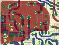
madisonears said:The schematic shows a 1 ohm resistor, R11, connecting the junction of C12, R10, and R13 to GND. I am far from being an expert at reading schematics and translating that to what is on a PCB, but the My Ref Twisted Pear board looks different from how I am reading the schematic. On the board, R11 connects only C21 to GND and is nowhere near R10, R13, or C12. Well, the dang thing works, so everything must be okay. I am not sophisticated enough to understand the function of R11. Can someone explain it, and why it's placed where it is on the PCB compared to what the schematic shows?
As you can see in the attached board schematic R11 is connected to the entire signal ground plane.
To this signal ground plane are also connected R10, R9, R13, C12 and input ground.
C21 is not directly connected to this signal ground.
Attachments
Hey Dario, nice to hear from you. Cool graphics.
Oops, I meant to write that, on the PCB, R11 connects C20 to GND, not C21. In the schematic, C20 goes directly to GND and is nowhere near R11. In the schematic, R11 appears to separate the 0 volt area from GND, but it doesn't do that on the PCB.
Looking at it again, it does serve to separate the input signal from the power ground area. Pretty clever layout, actually. I think I understand it now.
Peace,
Tom E
I am kind of wondering, looking at the circuit, it seems the design if current source design. Has anyone any experience how this would effect sound when used in multi-way systems where there are impedance peaks in the mid range? Intuition tells me that this will effect the overall frequency response of the system. I also recall that Nelson Pass did some research on this.
bluegti said:I have one board stuffed with Silmics and 22nF WimaFKP2. Unfortunately, I have to go out of town for 10 days so I won't have time to report back for a couple of weeks.
Any news?
SPECTACULAR MY REF FAILURE!
Just kidding. Yes, I already did have a failure, and I couldn't figure out the problem. I had a pair of spare boards, so I built a pair of new amps. I incorporated all of the previous upgrades and included some more. One of them is playing right now along with one of the older amps. The differences are subtle but meaningful to anyone who values good sound.
The new configuration:
All active components (chips, diodes, rectifiers, transistors) remain the same. Power supply caps reused from failed amp.
All electrolytics except C9 are Panny FM caps: C1, C2, C6, C11, C14, C15, C16.
All ceramic caps are Kemet Golden Max.
All other small value caps are now metallized polypropylene or film and foil WIMA MKP or FKP. C21 is 0.022uF WIMA FKP.
Most resistors, including R5, R6, R8, R9 (0.1%) are now PRP or Caddock. R1 and R4 are Caddock 2 watt 1%. R3 is now Caddock MP-930 with heatsink. R10 and R12 are Shinkoh tantalum.
C17, C18, C19, and C20 not used.
C9 is Blackgate Standard polarized, 220uF.
C13 is Mundorf Silver-in-oil, 0.68uF.
Binding posts are Vampire solid copper/gold plated.
I wanted to use a better relay, but I couldn't find any others that fit the board. I could have used one off-board, but decided against it. I guess that might be the only area I neglected.
Some of the parts are a tight fit, but only the input cap is off the board. I use it with one lead directly soldered to the RCA and the other lead soldered to the board, so it does not require any additional wire or joints. I used teflon tubing to insulate the leads.
So there is my fully "tricked out" My Ref. It is actually quieter than the already quiet original amp. With all equipment on and my ear directly at the speaker, I hear NOTHING without a music signal present. Once the music starts, it is incredibly beautiful, detailed, smooth, three-dimensional, dynamic, robust. Bass is very powerful and tight. Midrange is present and clear and has realistic tonality without coloration. Highs are airy, sweet, extended. Thick instrumental textures are properly delineated and distinct. I recently sold my previous reference amp, an ARC 100.2. These amps are now, indeed, my ref. They are very nearly the equal of the BAT VK60 monoblocks I once owned; actually, much better in some ways.
I have one more experiment to perform, and then I am off the upgrade merry-go-round. I want to try one more input cap: a Fostex film and copper/tin foil cap. I heard some things with the AudioCap Theta that I really liked that the Mundorf doesn't do as well, and I believe it's a result of the film/foil construction. The AudioCap was very three dimensional, but the Mundorf doesn't have quite the same width and depth. The AudioCap was a little too bright with etched detail, while the Mundorf has beautiful detail without any harshness or edge. I hope the Fostex will do it all correctly because it uses copper along with the tin that is in the AudioCap. I will report the results here.
Peace,
Tom E
madisonears said:The new configuration:
...
All other small value caps are now metallized polypropylene or film and foil WIMA MKP or FKP. C21 is 0.022uF WIMA FKP.
...
C17, C18, C19, and C20 not used.
I think we can all agree that this is the starting point for improving the MyRef.
Get rid of all AVX BQs, use Wimas instead:
C30 FKP2 1nF 63V
C21 FKP2 22nF 63V
C4, C5 MKP4 100nF 250V 7.5 mm lead spacing
C7 MKP2/MKS2 100nF-220nF 63V
C17, C18, C19, and C20 not used
I encourage everyone that wants to improve the amp to start with these mods.
Regarding C9, C13, C6, C11 there's no general agreement.
It would be nice if someone else apart me and Tom could experiment with C9, C6, C11 and report back to the forum their impressions.
madisonears said:I have one more experiment to perform, and then I am off the upgrade merry-go-round. I want to try one more input cap: a Fostex film and copper/tin foil cap. I heard some things with the AudioCap Theta that I really liked that the Mundorf doesn't do as well, and I believe it's a result of the film/foil construction. The AudioCap was very three dimensional, but the Mundorf doesn't have quite the same width and depth. The AudioCap was a little too bright with etched detail, while the Mundorf has beautiful detail without any harshness or edge. I hope the Fostex will do it all correctly because it uses copper along with the tin that is in the AudioCap. I will report the results here.
I do agree, film/foil caps are best here IMHO, when I've compared C13 caps the best were Mundorf Zn and Obbligatos, both film/foil ones.
Tom, have you tried a 10nF FKP2 bypass here?
I've had great results with it.
PS
The MCAP Zn bypassed with FKP2 is quite as transparent as DC coupling, no harshness and it preserve the original soundstage.
I've some news on a new position suitable for cap swapping
When I've ordered the kits and began the quest for alternative components I've considered also C32 as a cap that could be upgraded (it is directly in the signal path) and bought some 150 pF 100V FKP2s.
I've made a quick test on the beginning of this long adventure and it seemed to me that FKP2s in that position bettered the sound but in some way restricted soundstage.
Today I've been trying 150 pF CDE Silver-Mica in C32 position and found that they were better than COG ceramics, so I gave another try to FKP2s too.
Well they're even better than SM with both FMs and Silmics in C9 position but in different ways.
FMs gains a better soundstage and firmer bass while Silmics gains weight in the midrange (that they were lacking a bit) and a 'rounder' bass, both gains clarity and transparency.
With FKP2s in C32 the quality difference between FMs and Silmics is even more evident, IMHO.
I think that the other mods created the right context for C32 upgrading (particularly C21).
I suggest this mod to everyone in addition the the others baseline mods of the previous post.
audiosteve said:Dario,
I have not started to build my kit yet. Would you be kind enough to reiterate a summary of which caps should be changed to what in order to optimize the performance of this amplifier?
Thanks,
Steve
As Uriah stated it's just two post upper but no problem...
Get rid of all AVX BQs, use Wimas instead:
C30 Wima FKP2 1nF 63V
C21 Wima FKP2 22nF 63V (to be mounted in the bottom side of PCB)
C4, C5 Wima MKP4 100nF 250V 7.5 mm lead spacing
C7 Wima MKP2/MKS2 100nF-220nF 63V
C32 Wima FKP2 150 pF 100V
C13 Mundorf MCap 1.0uF 250V (low cost, perfect fit)
C13 Mundorf MCap Zn 1.2uF 250V (best but outboard)
C13 has to be bypassed by a 10 nF Wima FKP2
C17, C18, C19, and C20 are not used (leave positions void)
And finally the controversials:
C9 Elna Silmic II 220 uF 35V (tight fit)
C6,C11 Elna Silmic II 100 uF 35V
Uriah, any news?
Unfortunately yeah. Mine broke during my move to Texas. I was not careful with the heatsinks and they are light so they were only held in place by the fact that the LM3886 chip was bolted to it. So in the move of course they bounced around and broke the chip off of the board. It can be fixed but I am selling it to a friend and building an F5. Of course now there is a BA1 to build When will it end. I am also thinking that it might be easy to do a DAC since many manufacturers have eval boards I could use as a starting point. In the meantime I bought a TAmp from PartsExpress and run it from the computer. Its awesome for $40. Sound is nowhere near the MyRef but the soundstage is very large. I opened it up to see if I could mod it. That will be a hopeless endeavor except that I could replace the pot which I am sure would be a good improvement but I think I will just be happy with it and build the F5 then be ecstatic with that
To me if anyone is going to mod this MyRef you HAVE to remove C13 and put a wire in place of it then measure for DC. If it is still acceptable this is probably the best change you can make as it is very dramatic increase in quality. Then from that point get some LDRs and build a Lightspeed to drive them. After that I have not tried anything but removing a few 220nf caps from around the LM318 that I have mixed feelings about. Its different but the enhancements were offset by the negatives I guess. I suppose I was as happy with it as before I removed those caps, it just sounded different and the mid-soundstage was a bit pinched.
Uriah
When will it end. I am also thinking that it might be easy to do a DAC since many manufacturers have eval boards I could use as a starting point. In the meantime I bought a TAmp from PartsExpress and run it from the computer. Its awesome for $40. Sound is nowhere near the MyRef but the soundstage is very large. I opened it up to see if I could mod it. That will be a hopeless endeavor except that I could replace the pot which I am sure would be a good improvement but I think I will just be happy with it and build the F5 then be ecstatic with that To me if anyone is going to mod this MyRef you HAVE to remove C13 and put a wire in place of it then measure for DC. If it is still acceptable this is probably the best change you can make as it is very dramatic increase in quality. Then from that point get some LDRs and build a Lightspeed to drive them. After that I have not tried anything but removing a few 220nf caps from around the LM318 that I have mixed feelings about. Its different but the enhancements were offset by the negatives I guess. I suppose I was as happy with it as before I removed those caps, it just sounded different and the mid-soundstage was a bit pinched.
Uriah
udailey said:Unfortunately yeah. Mine broke during my move to Texas.
...
To me if anyone is going to mod this MyRef you HAVE to remove C13 and put a wire in place of it then measure for DC. If it is still acceptable this is probably the best change you can make as it is very dramatic increase in quality.
...
After that I have not tried anything but removing a few 220nf caps from around the LM318 that I have mixed feelings about. Its different but the enhancements were offset by the negatives I guess. I suppose I was as happy with it as before I removed those caps, it just sounded different and the mid-soundstage was a bit pinched.
What a pity!
Well, I think that with the Aleph you'll have some good time too
I agree that DC couple is better than any cap but MCAP Zns bypassed are quite as good and all my tests were done with DC coupled MyRef...
and differences were HUGE
ClaveFremen said:....and differences were HUGE
you mean the differences between DC coupled and using a Mundorf?
- Home
- Amplifiers
- Chip Amps
- The new "My Ref" Rev C thread