i bought a pair of 3886 for good measure and replaced one of them before wiring the transformer back in. strange and wonderful thing is, the amp was dead quiet the first time i fired it up. i couldn't believe it. i re fired it and once again, dead silence. whoopi! but after i played music through it once and unplugging everything, there is that hiss again, though much quieter than it was before.
....
only other tests i can think of are replacing the op-amps and stripping the amp from the chassis and heat sinks and try running it bare...
could anybody guess as to what's wrong? maybe i have fake smoothing caps. the noise i get is a hiss+low hum
did you connected PGND at least to safety ground?
Without that connection also mine has a slight hum.
i've read reports here of someone doing it and having the temp go up to 60 celsius. i would only be turning it on momentarily.
In this moment I'm running my modules with fortune heatsink (largerly inadequate) and temperature goes up to 70°C, so far they still works but I'm aware that soon I'll have to replace both LM3886s...
And that too hot temperature is with heatsinks... figure out without them... you'll have maybe 5 minutes...
.
1. What is the idle current or idle power dissipation of MyRefC?
2. Has anyone prepared a netlist or Spice model of the circuit?
1. Not much - it depends on the quiescent current of the LM3886 (which can vary a bit between samples). The LM318 consumes ~10 mA or less, and the relay consumes a few 10s of mA.
2. Very approximate - NatSemi never released an official Spice model of the LM3886. The few models that are floating around on the net are incomplete (don't model mute, SPiKe, etc.) or inaccurate. Likewise, there isn't a complete LM318 model around with all the balance and compensation pins correctly implemented.
My LTSpice simulations mostly use an LM1875 model for the Howland current pump, and the partial LM318 or LT318A model. It gives a rough idea of DC operating conditions and AC stability, no more.
.
could anybody guess as to what's wrong? maybe i have fake smoothing caps. the noise i get is a hiss+low hum
There are bound to be stray 50/60Hz magnetic fields around, regardless of the trafo and grounding. You can reduce it a bit by braiding the power cables to AC1/AC2/PGND so that the fields cancel. You will also need non-magnetic shielded cabling for the inputs. The input coupling cap should also have non-magnetic leads.
There will still be a slight residual hum, regardless.
1. Not much - it depends on the quiescent current of the LM3886 (which can vary a bit between samples). The LM318 consumes ~10 mA or less, and the relay consumes a few 10s of mA....
Thank you, I appreciate that.
Regards,
Rob
New PCB
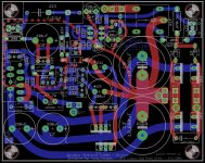
I'm thinking to make a small bunch (ca 10 boards) of new boards according to my objectives:
So any suggestion, improvement and/or feedback is welcome and appreciated
I'm thinking to make a small bunch (ca 10 boards) of new boards according to my objectives:
- 16 mm caps for C1, C2, C9
- 12.4mm caps for C6, C11
- SMD current pump, opamp, and compensation network like in the Evolution
- most critical component thru-hole for maximum customization
- most critical resistors 1/2W rated
- C7 and C8 ground also on the bottom layer
- MC7812/MC7912 PS, easier to upgrade with the various shunt regulators available
So any suggestion, improvement and/or feedback is welcome and appreciated
Attachments
thanks, bob. i'm gonna have to do something like that.
oops, my apt has no access to safety ground! does this mean i should wire from chassis to pcbs? the hum i'm gettin also comes with a high freq hiss. it's like hum, white noise, and hiss all rolled into one mysterious package.
oops, my apt has no access to safety ground! does this mean i should wire from chassis to pcbs? the hum i'm gettin also comes with a high freq hiss. it's like hum, white noise, and hiss all rolled into one mysterious package.
"SMD current pump, opamp, and compensation network like in the Evolution"
Can you explain the advantage/improvement of this part of your design?
Regarding the current pump SMD permit much shorter feedback loops and much lower inductance, improving stability.
When Mauro presented the MY_EVO (Evolution) he clearly stated that the SMD compensation network made a big difference for stability.
Also the SO8 opamp permit shorter paths and, in my experience, SMD opamps sound better than DIP counterparts.
Dario,
Looks like you have learned a lot! Designing your own boards is pretty sophisticated.
This is a two-sided board, but you have eliminated the ground plane. I hope that works out okay.
I like the wider traces, but is there any drawback to making them so big? Chance of introducing noise? I've never worked with SMD components, but a lot of people seem to have no trouble with it. I guess it's an aquired skill.
Peace,
Tom E
Hi Tom,
this PCB is the last version of that 'joke' that I've posted last year... but now I'm pretty confident it will work.
Though I'm still working on it, optimizing.
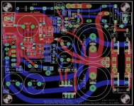
No, I've left it drafted so underneath traces are more clear... see the attachment for the complete version.
I don't know, it's one of the feedback I'm waiting...")
I've choose not incredibly small components, they're pretty big for SMD standards...
Even soldering it's not too difficult, the secret is thin solder (0.5mm diameter), tacky flux and tweezers.
Looks like you have learned a lot! Designing your own boards is pretty sophisticated.
this PCB is the last version of that 'joke' that I've posted last year... but now I'm pretty confident it will work.
Though I'm still working on it, optimizing.
This is a two-sided board, but you have eliminated the ground plane. I hope that works out okay.
No, I've left it drafted so underneath traces are more clear... see the attachment for the complete version.
I like the wider traces, but is there any drawback to making them so big? Chance of introducing noise?
I don't know, it's one of the feedback I'm waiting...
I've never worked with SMD components, but a lot of people seem to have no trouble with it. I guess it's an aquired skill.
I've choose not incredibly small components, they're pretty big for SMD standards...
Even soldering it's not too difficult, the secret is thin solder (0.5mm diameter), tacky flux and tweezers.
Attachments
Last edited:
So any suggestion, improvement and/or feedback is welcome and appreciated
Hi Dario - looking good. I've only briefly looked at the layout, so here are a couple of quick suggestions:
1. If they aren't already in 35mm diameter, make C3 and C8 35mm. There's more choice of good electrolytics in 35 mm.
2. If you leave the LM318 in DIP08, it will allow the LF01 module (using an SMD LM318M) as a pluggable option, in addition to DIP08 LM318N/P/J.
just got done installing k72 teflons in c4 & 7. i used 2.5inchs of ofc wires to put them on the sides of the pcbs. improvements are definitely there but the highs have become accentuated to where it's once again a bright sounding amp. and yet coming from mpk4 & fkp2, this is more transparent and lively. and the bass is deeper, quite a bit so. i'd say it's a huge success if it wasn't so bright sounding. i probably should've gone for PIOs... );
Last edited:
"I've never worked with SMD components, but a lot of people seem to have no trouble with it. I guess it's an aquired skill".
I've only done a few - but super pointy tweezers (from drugstore), good liquid flux and an illuminated magnifying glass make it pretty easy.
Here's a great video:
Surface Mount Soldering 101 Video
I've only done a few - but super pointy tweezers (from drugstore), good liquid flux and an illuminated magnifying glass make it pretty easy.
Here's a great video:
Surface Mount Soldering 101 Video
could anybody guess as to what my problem is?
ok. i was able to borrow a local diy-er's gainclone, and...
THE GAINCLONE SOUNDS MUCH BETTER!!
the bass and transparency of it just humiliates my myref which leaves me no doubt that there's something wrong with the unit. i've checked the parts layout at least a dozen times but here's a picture of how i received the amp.
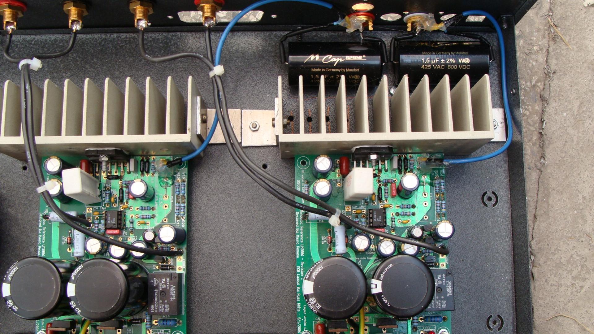
the weak bass has been persistant from the start. and having listened to a gainclone, i can now say transparency too suffers greatly. also the heatsinks on mine barely gets toasty. bathwater warm at the most. something's definitely underpowering the chips but i won't be able to investigate further until my multimeter arrives that i haven't yet ordered :/. please gents, help.
ok. i was able to borrow a local diy-er's gainclone, and...
THE GAINCLONE SOUNDS MUCH BETTER!!
the bass and transparency of it just humiliates my myref which leaves me no doubt that there's something wrong with the unit. i've checked the parts layout at least a dozen times but here's a picture of how i received the amp.
the weak bass has been persistant from the start. and having listened to a gainclone, i can now say transparency too suffers greatly. also the heatsinks on mine barely gets toasty. bathwater warm at the most. something's definitely underpowering the chips but i won't be able to investigate further until my multimeter arrives that i haven't yet ordered :/. please gents, help.
Last edited:
- Home
- Amplifiers
- Chip Amps
- The new "My Ref" Rev C thread