Man... i feel your pain, really.
I fired up the other channel, LED glows and relay clicks. But dc offset numbers fluctuate all over the place. So i'm not sure what gives. Couldn't be a zener/diode orientation problem since both are arranged exactly the same way. Strangely, the board that works is the one that i did first and was considerably more rough with the handling.
I'm wondering if it's possible that the 3886 and/or 318 chip is somehow faulty. Would that prevent the amp from starting up at all?
.....I'm wondering if it's possible that the 3886 and/or 318 chip is somehow faulty. Would that prevent the amp from starting up at all?
I have replaced both of those twice without success.
Most definitely! You did such an awesome job with this huge group buy and i'm immensely grateful to youThere were no issues with the boards. I would never do you all a disservice like that.
I can't help but think that it's a problem with one of the key components. Can faulty resistors (potential overheat during soldering) prevent the board from powering up? Or is it a potential diode, relay, 318 or 3886 problem?
Also, does anyone know why the functioning board has a dc offset value that fluctuates wildly?
I'm wondering if it's possible that the 3886 and/or 318 chip is somehow faulty. Would that prevent the amp from starting up at all?
Without actually inspecting and measuring stuff on the actual faulty board, it's hard to say. However, there are a few things that can be checked.
1) Ensure that the LM3886T metal tab does not come into contact with the heatsink or any other piece of grounded metal. The tab is connected to V- internally, and any contact with ground will cook the LM3886T, no exceptions.
2) Some LM318 chips will cause the MyRef to latch up high on the output and the relay won't fire (that's the DC protection at work). This problem is usually solved by swapping in other LM318s until one works. It's not that common (maybe 1 in 10), and confined only to NatSemi parts, AFAIK.
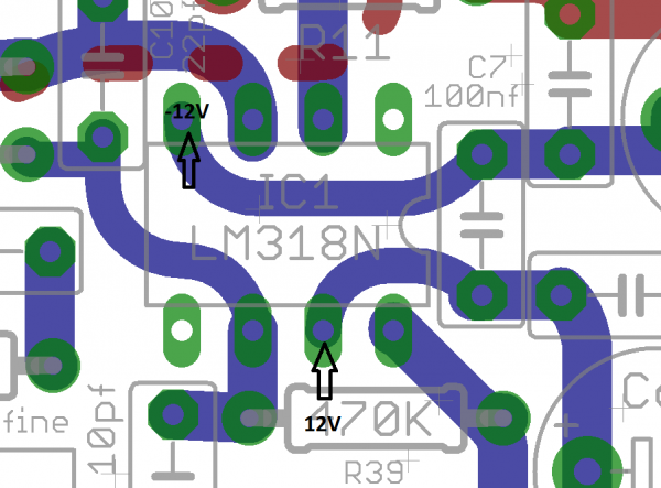
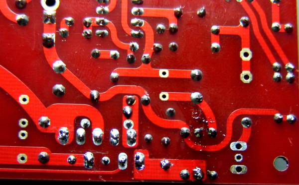
3) Inspect the orientation of all parts and check all joints for shorts/opens. The joints near the small-signal ground plane are prone to shorts to the ground-plane. Re-flow joints that look suspect, and clean the flux to get better visibility during inspection.
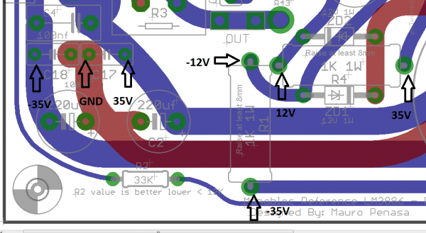
4) Measure the trafo O/P and rail voltages to the LM3886 and the LM318.
A flying lead/probe test was done on all the boards. These boards were made from twisted pears gerbers. There are no thin or close together traces. You can literally see them all. Many people have seen the same problem and discussed it here and other myrefc threads. Most found an answer. A deeper understanding of the circuit may not help at all. It's not a difficult circuit to start with. Smart circuit though. The problem may be out of the box, if you will. It may just not have enough current to the relay. I don't know and none of us can know for certain. We just throw out plausible suggestions.
Cersepn... I am betting your offset is a grounding issue and please check for resistance from tab to sink.
Alligator clips and a dmm are a great solution to tracking down grounding problems. Two clips connected with a wire. Ground one to earth or another ground point and poke around with the other end on other grounds while watching offset. Especially check potentiometer grounding and its casing.
hehe just ordered russian teflon .1uf caps for c4,7. any reason why i shouldn't use them besides the real estate problem?
They won't fit easily, and the leads will be long, contributing to lead inductance of about 0.7nH/mm. Not huge, but enough to contribute to a HF LC tank circuit that will have sufficient extra impedance at much lower frequencies.
Go ahead and try them out, but they probably won't beat a flush-mounted MKP2 or MKP10 at C4. Likewise, the only real challenger to a 10nF FKP2 at C7 that I've found is a flush-mounted 10nF Rifa PFE225, but YMMV. Rifa PFRs in the 4.7 to 22 nF range may be worth a try.
enough to contribute to a HF LC tank circuit that will have sufficient extra impedance at much lower frequencies.
i'm sorry, Siva. could you explain this to me in a layman's term? all i know is how to hold a solder at this point, carelessly...
i should add that i've put mkp4 in c7 after finding fkp2 to be too soft in the long listen, and mkp2 having a slight recess in the midrange in contrast to mkp4- most noticeable with background vocals being lost in the mix. they're mounted underboard with about 5mm of leads sticking out and it still sounds superior to me than its flush mounted competitors
")
on a side request, does anyone have the link to a .txt file where mauro talks about regulators for the op-amp and possible usage of pp caps for c9? i did a hd sweep coulpe days ago and now it's gone.
Last edited:
Hi Uriah,
In no way was I implying that you or any other source for the V1.2 PCBs did or intended to do anything of your own volition that reflected a desire to do less than your best. If I offended you or you feel my comments on my experience with my builds reflected poorly on you or your reputation, I openly and sincerely offer my apology. If one looks around various threads it will be apparent I have often given praise and recommendations to others based on your professionalism, quality of product and flat-out willingness to assist with whatever problems arise. Your Lightspeed and the Lighter Note are the heart of my LM3886 endeavors and function in a way that causes me pause when considering experimenting with any other volume adjustment method.
My path led me to my stated suspicion due to the following steps taken by me:
1. I confirmed all the above mentioned measurements on the original components.
2. I replaced all the parts as suggested by the various forum members.
3. I transferred everything to a fresh board.
4. Re-ordered everything except the matched resistors + R1 & R4 and repopulated the board - including new LM3886s.
5. Swapped out many components from a working build (including C3 & C8) - everything worked properly on the V1.3 board - nothing added functionality to the V1.2.
6. Installed a socket for LM318 and have tried no less than 6 chip - both flavors.
7. De-soldered the relay and confirmed operation out of circuit.
8. Purchased three new relays and have installed two so far.
9. Bought a new digital meter and confirmed all the values of the parts and test points within my understanding.
I don't think it totally unreasonable, at this point, to start suspecting the one constant, the PCB, as a possible source of the problem. I have even gone so far as to send out some requests for a procedure to isolate the power components on a separate breadboard for further investigation.
It would be logical and much more cost effective for me to just move on and enjoy the successful MyRef builds and try to adopt the new and interesting mods and swaps being discussed here, but my curiosity (and probably some ego) keep bringing me back to this challenge.
As always, I'm open to all suggestions and willing to try till I get some music from this build. I don't however, wish to waste anyone's time or cast dispersions in any way.
Highest Regards To All
Last edited:
i'm sorry, Siva. could you explain this to me in a layman's term?
The lead inductance, L, combines with the capacitance, C, to create a series LC-tank circuit with resonant frequency, f = 1 / (2*pi*sqrt(LC)). Depending on the value of L and C, this resonance will be in the range of 100s of kHz to a few MHz. As it approaches the resonant frequency, the impedance of the tank circuit will increase, essentially neutralizing the function of the bypass capacitor near the resonant frequency. This is undesirable - we want the bypass capacitor to look like an AC short-circuit well into the 100 MHz region and above, to keep the opamp stable over its entire gain-bandwidth (GBW) product range.
It's therefore necessary to try to make the resonant frequency as high as possible, which implies keeping the lead inductance L as low as possible, which implies keeping the lead length as short as possible - not more than 10 mm in total, if possible.
Can you give a more detailed description of the MyRef "small-signal ground plane" and possibly name the components and their location on the board.?
Hi Bob - it's the copper plane on the component-side of the PCB near the LM318 and its associated components, including R5..R13, C9, C10, C12, C13, C21, C30, C32, etc.
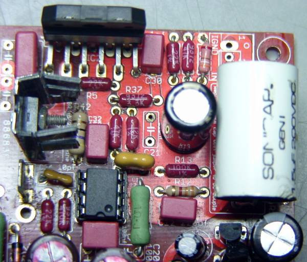
Nothing Yet. Found a chip on R9 and replaced it with one from a backup set. Readings as of today (pics complements of Dario)
Pin7 Vcc+ is reading 6.8V. All others readings are as listed. I can find no shorts or opens in the small ground plane area.

The Mystery Continues.
(For you English majors out there I did mean aspersions in my previous post. One must wake up before one starts typing)
Pin7 Vcc+ is reading 6.8V. All others readings are as listed. I can find no shorts or opens in the small ground plane area.
The Mystery Continues.
(For you English majors out there I did mean aspersions in my previous post. One must wake up before one starts typing)
I was never able to identify the fault in my amp that didn't work. I have made seven complete amps on green and red boards, plus reworked with mods on a lot of those. Of those seven, only one did not work upon first try. Another one I blew up with careless soldering of too many mods (there was a tiny flash near the 318 upon power up!), and it was thrown away.
After much searching and hair-pulling, I rebuilt the amp that didn't work with new chips and a new board and everything was fine. While I was removing parts from the faulty amp to put into the new one, I noticed a tiny "disc" of solder on one of the legs of the BG. I think it had shorted to the ground plane somehow, or perhaps even to the other leg. I never would have seen it without removing the part, as the leads are pretty well hidden by the cap itself.
If I were to change anything on this board, it would be to put a bit more space around the pads on the top of the board that are within the ground plane. When you're soldering parts from the bottom of the board, it is possible for solder to wick along the leads onto the top side and fill or perhaps overflow the pads on top.
Sorry that you guys are having problems.
Peace,
Tom E
is it safe to assume that there's something wrong with the amp if the bass is weaker than an under built chip amp? my modded topping tp20's bass is so much deeper and more defined that it's not even a comparison. myref also has a humming issue that i wonder if it'll improve the bass when i fix it.
- Home
- Amplifiers
- Chip Amps
- The new "My Ref" Rev C thread