Is it possible to run Rev C at lower gain? Say 15x voltage gain? My speakers have ~97db of sensitivity, and a 15x voltage gain is just about right with my plain (i.e., not composite) gainclone. I tried to read as many pages as possible here, but have not seen any specific mod to lower the gain to below 20x. Thanks!
Please, don't do it. At least for now. The gain structure of a composit amplifier is a finely tuned, sensitive design.
Instability lurks behind the corner, it should be done in a calculated, simulated measured, tested way.
Very easily the result obtained could be an oscillating amp.
Ps: from my side, maybe I will venture in this grey zone, to move downwards a bit, with the gain.
I will do it for the versions more easy to simulate, control. The compensations will be changed, for sure. And testing will be fundamental.
Ciao, G
Please, don't do it. At least for now. The gain structure of a composit amplifier is a finely tuned, sensitive design.
Instability lurks behind the corner, it should be done in a calculated, simulated measured, tested way.
Very easily the result obtained could be an oscillating amp.
Ps: from my side, maybe I will venture in this grey zone, to move downwards a bit, with the gain.
I will do it for the versions more easy to simulate, control. The compensations will be changed, for sure. And testing will be fundamental.
Ciao, G
I look forward to it when that comes. It would be great if MyRef is offered in a high-gain version and a low/lower gain version.
Btw, I do appreciate you experimenting with OPA627 with the MyRef -- 17 years ago, when "Tangentsoft" was comparing opamps, I found that OPA627/37 was by far my favorite. It has that magical cleanliness and "settledness" to its sound.
If you need less gain, the more straightforward way with this amp is to install a fixed value divider, with the best quality resistors one can get.
Like: 5k/5k would give a bit less than half total gain.
The input resistance would shrink from 100kohm to 10kohm. But, if you are in need of doing it, for me it means you are using some preamp or modern, hot output dac, with very low output impedance and high drive capability.. So I think 10kohm os AOK.
Then, while you are at it, this divider would be followed by R12 (3,3kohm) placed in series on the input.
Now, with the divider in place, and an equivalent source resistance of 2,5kohm, one can just swap out R12 from 3,3kohm to 680ohm.
So, even with the new divider, the noise generated by the input circuitry would remain unchanged, the gain halved, the input RF filter unchanged, input impedance decreased to 10kohm.
If you need less gain, the more straightforward way with this amp is to install a fixed value divider, with the best quality resistors one can get.
Like: 5k/5k would give a bit less than half total gain.
The input resistance would shrink from 100kohm to 10kohm. But, if you are in need of doing it, for me it means you are using some preamp or modern, hot output dac, with very low output impedance and high drive capability.. So I think 10kohm os AOK.
Then, while you are at it, this divider would be followed by R12 (3,3kohm) placed in series on the input.
Now, with the divider in place, and an equivalent source resistance of 2,5kohm, one can just swap out R12 from 3,3kohm to 680ohm.
So, even with the new divider, the noise generated by the input circuitry would remain unchanged, the gain halved, the input RF filter unchanged, input impedance decreased to 10kohm.
Yes, I agree that a voltage divider would work perfectly in the most practical sense. I however strongly follow the KISS principle (why I first adopted the original gainclone), and so I really prefer not to have additional components in the signal path. I also do not want to throw away useful signal, even if just theoretically.
Ok, now I get it.
While we can help since the two amps are strictly related you're on the wrong thread... the right one is this: The new "My Ref" Rev C thread
Please post there, I'll give you my suggestions.
Quote:
Originally Posted by ClaveFremen View Post
I'm fine, simply at work night & day, 11PM here and I'm patching several customers Exchange servers for a zero day vunerability..
Puffin can you share the exact BOM you used so that I can help you identify the possible culprits?
Anyway if the HF lack is serious I would suspect an error on the LM318 compensation network.
If not C13 and C9 have a big impact on sound.
Glad to hear that you are well. CV-19 has made the world a very different place.
This is the BOM I used :-
Number Desc 1 Desc 2 Desc 3 Source Part Number per count total
D1-D3 1N4001 1A - 50V Diodes On Semi Digikey 1N4001RLOSCT-ND 0.224 3 0.672
Q2-Q3 BC546 NPN Bipolar Transistor On Semi Digikey BC546BOS-ND 0.164 2 0.328
Q1 BC639 NPN Bipolar Transistor Fairchild Mouser 512-BC639 0.18 1 0.18
ZD1-ZD4 BZX85-XX 12V 1.3W Zener Diode Fairchild Mouser 512-BZX85C12 0.08 4 0.32
C7, C23 100nF MKT (box) 50V Capacitor Panasonic Digikey P4593-ND 0.108 2 0.216
C10, C25 100pF MKT (box) 50V Capacitor Panasonic Digikey P4570-ND 0.072 2 0.144
C12, C27 220pF MKT (box) 50V Capacitor Panasonic Digikey P4574-ND 0.072 2 0.144
C4, C5, C19, C22 100nF MKT (box) 100V Capacitor Panasonic Digikey P4656-ND 0.159 4 0.636
C13, C29 1uF MKP (box) 50V Capacitor Panasonic Digikey E1105-ND 0.741 2 1.482
C9, C14, C22 220uF Radial 50V EL Capacitor Sanyo AX Bdent 63MV220AX 0.4 3 1.2
C1-2, C17-18 220uF Radial 50V lowESR EL Capacitor Sanyo FZ Bdent 50MV220FZ 1.04 4 4.16
C3, C8, C20, C28 10000uF 50V EL Caps Sanyo DAC Bdent 50PL10000DAC 4.29 4 17.16
C15 22uF Radial 25V EL Capacitor Sanyo SAX Bdent 25MV22SAX 0.18 1 0.18
C6, C11, C16, C21, C26 100uF Radial 25V EL Capacitor Sanyo AX Bdent 25MV100AX 0.18 5 0.9
U1-2 LM319N DIL Op Amp National Semi Digikey LM318N-ND 1.017 2 2.034
IC1-2 LM3886 Amp National Semi Digikey LM3886TF-ND 4.16 2 8.32
D1, D5 8A 400V Bridge Rect. Diodes GBT804 Mouser 621-GBJ804 1.52 2 3.04
R5, R8, R28, R31 22K0 .25W .1% IRC .1% RC55 Mouser 66-RC55-D-22.1K 0.96 4 3.84
R6, R9, R29, R32 47K0 .25W .1% IRC .1% RC55 Mouser 66-RC55-D-47.5K 0.96 4 3.84
R2, R25 33K .25W 1% KOA Spear Mouser 660-MF1/4CL3322F 0.12 2 0.24
R7, R30 12K0 .25W 1% KOA Spear Mouser 660-MF1/4CL1202F 0.12 2 0.24
R10, R33 390 .25W 1% KOA Spear Mouser 660-MF1/4CL3920F 0.12 2 0.24
R11, R35 1 .25W 1% KOA Spear Mouser 660-MF1/4CL1R00F 0.17 2 0.34
R12, R34 3K32 .25W 1% KOA Spear Mouser 660-MF1/4CL3321F 0.12 2 0.24
R13, R36 100K .25W 1% KOA Spear Mouser 660-MF1/4CL1003F 0.12 2 0.24
R15-18 75K .25W 1% KOA Spear Mouser 660-MF1/4CL7502F 0.12 4 0.48
R19 10K .25W 1% KOA Spear Mouser 660-MF1/4CL1002F 0.12 1 0.12
R20 47K .25W 1% KOA Spear Mouser 660-MF1/4CL4702F 0.12 1 0.12
R21 220K .25W 1% KOA Spear Mouser 660-MF1/4CL2213F 0.12 1 0.12
R22 8K2 .25W 1% KOA Spear Mouser 660-MF1/4CL8251F 0.12 1 0.12
R23 6K8 .5W 5% KOA Spear Mouser 660-MF1/2CL6811F 0.14 1 0.14
R1, R4, R24, R27 1K 1W 5% Vishay-Dale PRO1 Mouser 594-5073NW1K000J 0.16 4 0.64
R14 470 1W 5% Vishay-Dale PRO1 Mouser 594-5073NW470R0J 0.16 1 0.16
R3, R26 0.47 5W WW Huntington Elec Digikey ALSR5F.50-ND 1.35 2 2.7
RELAY1 24VDC 2sc 8A-250V 24v 8A Omeron Mouser 653-G2RL-24B-DC24 4.1 1 4.1
PL1-8 Faston Connectors (PCB Mount) Digikey A24742-ND 0.055 8 0.44
However, not all the components were of the same manufacture as the BOM, but the values were the same.
I thought I ought to add in relation to C9 & C13, I have DC coupled the boards and so there are no C13's fitted. Should I still expect a major difference in HF SQ simply by replacing C9?
Puffin... where did you took this BOM? It looks wrong to me, it seems not for Twisted Pear boards but for the original Penasa's stereo board...
I can't also find the compensation caps... and as I've said in the FE threads I suspect the problem is in the compensation...
Can you post some pictures of your populated boards so that we can check which ones they are?
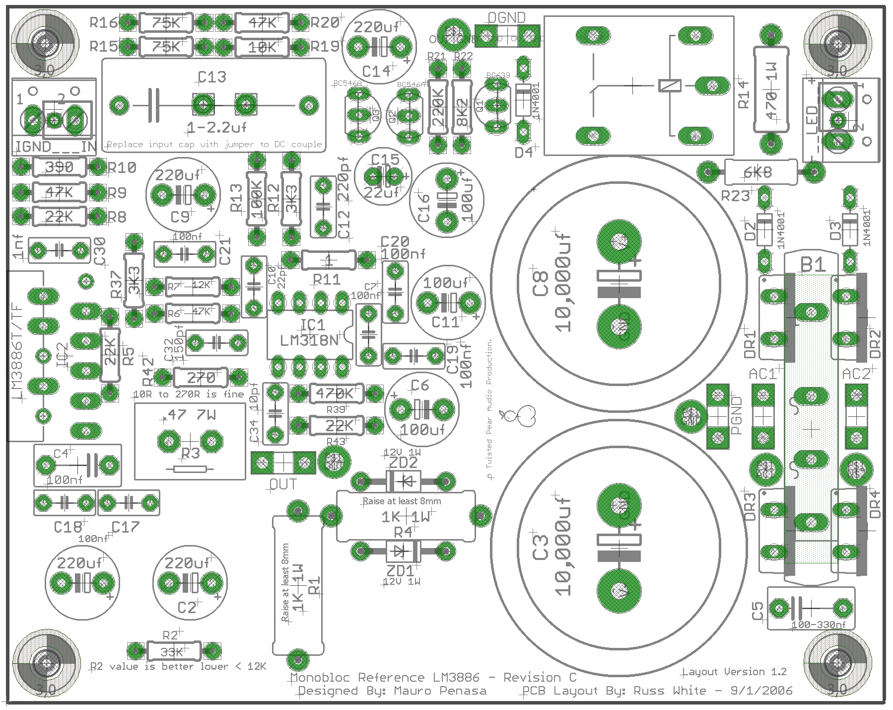
This is a TP board:
This is an original stereo Penasa's board:
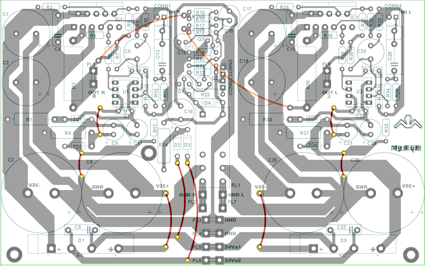
You will notice that components numbering is different...
I can't also find the compensation caps... and as I've said in the FE threads I suspect the problem is in the compensation...
Can you post some pictures of your populated boards so that we can check which ones they are?
This is a TP board:
This is an original stereo Penasa's board:
You will notice that components numbering is different...
Attachments
Last edited:
Hi Dario, thanks for your reply. I followed the values for the components from both the BOM and the silk screen printing on the board. It is unlikely (but possible) that I used one or more incorrect values when soldering them. I normally check all resistor values with a multimeter before soldering even if the strip of resistors is marked with the value.
I have a capacitor and semiconductor checker that I also use to confirm values before installing.
I will take some good pics of the boards and post them later. Would I be right in saying that you feel that the lack of HF is more than simply trying a different flavour of C9?
I removed C13 and DC coupled to see if this made any difference....it didn't.
Rob.
Dear Rob,
There seems to be an ongoing mis-understanding here..
This project has a very long history.
The different sections of this history could be called a completely different product. (soundwise).
Small particular changes in the topology, but very strong changes in the BOM, usually.
So it is not directly useful to refer to a 'BOM' here: the one that You applied, and probably had to, has completely nothing to do with the BOM (and sound) that Dario has been concentrating on. The origin and targets of that BOM that You had found, is a bit faded, too.. At least I would have difficulties to recollect..
So I think what could be useful here is maybe to rethink Your board in the terms of a new BOM, more similar to that of the FE design..?
Also: in the course of the years, the compensation formula for this amp had changed. Because the original project owner, Penasa had his own evolution of approach.. So, what is Dario refers to is that the compensation scheme, as applied to Your particular board, is still very much unclear.
It's not like You did change something. It's like we don't know, according to what scheme did You assemble that board..
Again, that project is quite much different from the ongoing FE design (as it turns out now, looking at your values..)
So there is not much help that we could give, as referred to that scheme applied in that particular realization.
Dario (but also us others) could give only hints, how to change it so as go to the FE design direction.
My feeling in particular is that your compensation capacitors are all MKT versions. That is in itself an explanation to what You hear now..
Ciao, george
My feeling in particular is that your compensation capacitors are all MKT versions. That is in itself an explanation to what You hear now..
George, you're right about the MKTs but I think it's much worse...
On Puffin's BOM he has 100pf on C10...Can you imagine how disrupted would be the amp performace if the Rev C C10 is 100pF?
")
Attachments
Last edited:
Ah ok!!
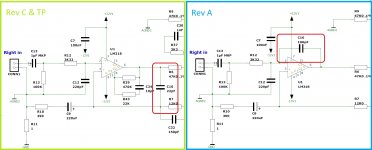
That is the famous RevA compensation scheme..
I am even hesitating to write down Rev A, because todays it means something totally different, like the state of the art..
Yes, Puffin, that was the very first version, realization of this MyRef project.
Mauro Penasa himself had proceeded forward from that vompensation scheme, very quickly.
And there had been always fans of that scheme, because it gave a 'mellow' sound character, with respect to the RevC compensation scheme, which is much more resolutive..
Just to put it in a historical context...
Ciao, George
Thank you George and Dario. So.... can either of you advise in addition to changing C10 to 220pf which other caps and values I should change?
It’s 22pF... nevertheless I will tell nothing more until you post pics of the boards, possibly with macros on lm318 and surrounding parts.
Ok, I have attached what I hope is a clear enough pic of the area around the LM318. I must apologise as I seem to be getting confused (I have a significant birthday today which rhymes with "Clickety Click") I have in fact used a 22pf at C10. Look forward to hearing where I might go from here. Rob.
UPDATE: It would appear that I have used the correct values at C7, C10, C32, C34 although my choice of capacitor may be bad.

) I have in fact used a 22pf at C10. Look forward to hearing where I might go from here. Rob.UPDATE: It would appear that I have used the correct values at C7, C10, C32, C34 although my choice of capacitor may be bad.
Last edited:
Gosh! Has anyone been able to do any measurement to really show relations between design and sound? I had tried some changes between voltage vs current gain compensation, and see some interesting trends. Still have yet to get back to working on it.
The 318 basically is implemented to work as an integrator in a control system. It dominates how well the feedback error is compensated to commanded current. This in turn would actually depend on the speaker design to come out with an optimum MyRef design. So not one single design will be optimized for all loudspeakers.
The 318 basically is implemented to work as an integrator in a control system. It dominates how well the feedback error is compensated to commanded current. This in turn would actually depend on the speaker design to come out with an optimum MyRef design. So not one single design will be optimized for all loudspeakers.
Geoff!
Good eyes. THIS is THE problem of Puffin..
C12 is an MKT 22nF instead of 0,22nF capacitor..
Let's put it like this: the original input filter R13, C12 - defines a cca 0.75uSec tau = ~200kHz - 3dB pole at the input.
With 100 times the capacity value, Puffin now has a 2kHz - 3dB input filter on his amp...
No wonder his experience is not at the maximum level..
Apart from this, the configuration on board is that of MyrefC, that is OK.
- Home
- Amplifiers
- Chip Amps
- The new "My Ref" Rev C thread