I'm curious about operating one of our favorite chip amps corresponding to a 10k balanced amplifier (whether its balanced or not).
We know that setting the input impedance resistor to 10k does result in lower DC offset.
And, we know that "when in doubt" then our non-inverting amplifier is supposed to resemble a balanced amplifier, "as a starting place for design," because that has the same structure on both its inverting and non-inverting inputs.
Yesterday, I made an amplifier with 1 pair of 10k and 1 pair of 330R (schematic to follow soon).
This had less "shout" and more available power than the usual 10k input impedance and 20k feedback resistor arrangement. DC offset was approximately 20mv.
Has anyone tried options like these?
Pair of 10, pair of 330R?
Howabout pair of 1k, pair of 33R?
Or what about pair of 100R, pair of 3.3R (can use headphone amp pre)?
Schematic
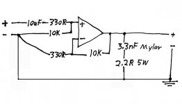
I'm thinking. . .kind of like a balanced amplifier, as in whatever is done to the op amp's - input, then do so to the + input as well.
The 10uF capacitor shown is an economical speciality model, widely known in prosound, a 10uF Nichicon ES 50v. On this one, input is short pin (marked "BP), output is long pin, just like a polar cap.
You can substitute any model cap you like but don't first run the signal through a resistor, otherwise you will have duplicated the noise of a defective capacitor. Exception: The output resistor of a buffer/preamp can be paralleled with an inductor.
Problem:
Duplicating the noise of a defective capacitor is exactly what would happen if we put a potentiometer at the input + and - shown below. If it wasn't all the way up all the time, then a pot would put series resistance at the input of the capacitor, creating distortion. Example: Any setting except for "full blast" on the pot, then represents an extremely high ESR cap, such as so defective that it should never be used in a circuit.
So, now the question is, if we're not using a buffer, and we want the circuit to resemble a balanced amplifier as closely as possible, then where do we put the pot?
Attachments
Hi,
your schematic shows the inverting pin fed from 330r//10k.
The non inverting pin is fed from 10k only.
This is not matched.
If you add a DC blocking cap to the non-inverting input you should also add a DC blocking cap to the inverting input, if you require matching of resistances/impedances.
Now in plain electrical talk:
what does this mean?
where does this conclusion come from?Duplicating the noise of a defective capacitor is exactly what would happen if we put a potentiometer at the input + and - shown below. If it wasn't all the way up all the time, then a pot would put series resistance at the input of the capacitor, creating distortion. Example: Any setting except for "full blast" on the pot, then represents an extremely high ESR cap, such as so defective that it should never be used in a circuit.
....and more available power than the usual 10k input impedance and 20k feedback resistor arrangement.
AndrewT said:Hi,
your schematic shows the inverting pin fed from 330r//10k.
The non inverting pin is fed from 10k only.
This is not matched.
If you add a DC blocking cap to the non-inverting input you should also add a DC blocking cap to the inverting input, if you require matching of resistances/impedances.
. . .
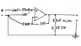
Here's an improved drawing that may show more clearly. I just don't see how either has a paralleled 330R and 10k. Its not intended that way. Would you fix it for me?
The capacitor specified has 0.5 ohms resistance to passing an audio signal. I find it unnecessary to install either an additional 0.5 ohms or an additional capacitor to the inverting input of the amplifier, as its tolerance as is already tighter than the variations of its 5% resistors.
It would be detrimental to add the series resistance of a potentiometer to the input filter capacitor because. . . Even a random choice of a 4.7uF 50v capacitor would be considered defective and in need of replacement if its resistance to an AC signal exceeds 3 ohms, because that does unlevel its performance to some extent. . . which is then magnified by the gain of the amplifier into a distortion.
For some reason that I am unaware of, one can add up to, approximately, 2.5R to the input side of a capacitor (in this example) without incurring noticable distortion. However, the output side can have, approximately, 470R.
To me, this means that from 220R (high gain for mp3/PC) to 470R (low gain for line level) are valid resistor values to use, and will not degrade the performance of the input filter capacitor.
So, that may explain why the resistor values are 10k with 330R.
Attachments
OH, I'm supposed to have a resistor in-between the + and - inputs, aren't I?
Honestly, I'm having so much trouble remembering stuff at the moment.
EDIT: And, Oh no! I thought I had the bandwidth the same on both sides, but I've actually lowered the pitch by the gain factor (30 times), haven't I?
EDIT2: Should the input impedance be higher or lower than the nfb resistor, and how many times? Its usually only documented as 2x.
it's just such a shame that it all gets buried in gobble de gook to the extent that beginners don't have the knowledge to recognise it for what it is.danielwritesbac said:.........Honestly, I'm having so much trouble making up stuff at the moment.....
AndrewT said:
quote:
Originally posted by danielwritesbac
.........Honestly, I'm having so much trouble making up stuff at the moment.....
I'm just trying to figure out why this amplifier is so different from its near-identical twin on the same PCB, with the same components. I haven't a clue!
AndrewT said:it's just such a shame that it all gets buried in gobble de gook to the extent that beginners don't have the knowledge to recognise it for what it is.
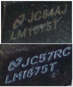
Its not about that. I'm not exactly recommending this amplifier. It frequency response is poor, but its unreasonably powerful. I just want to know what's up with it. Do you suppose the chip is a fake? How do I tell?
Attachments
")
the weird conclusions never stop.danielwritesbac said:... It frequency response is poor, but its unreasonably powerful. .........
a high pass filter @~1.6Hz and no low pass filter, where does "response is poor" come from?
Voltage gain of ~ +29.9dB, where does "unreasonably powerful" come from?
Have you measured something and forgotten to pass on the results that substantiate your claims?
AndrewT said:the weird conclusions never stop.
a high pass filter @~1.6Hz and no low pass filter, where does "response is poor" come from?
Voltage gain of ~ +29.9dB, where does "unreasonably powerful" come from?
Have you measured something and forgotten to pass on the results that substantiate your claims?
Oh, no I didn't measure too carefully. I hadn't intended to do much with this amplifier. But, I was curious.
I connected it to my PC. There's no potentiometer in use. I hadn't changed the position of my digital volume control. The new amplifier exceeded the mechanical limits on 8 ohm, 85db efficient speakers. (unreasonably powerful for an LM1875) And, it nearly sent me off my chair with the surprise of it.
Its near-identical twin couldn't have exceeded the speaker.
EDIT: Its my understanding that LM1875 couldn't do much more than 43 watts output, and that would require 6 ohm speakers along with a bit too much voltage. Well, I didn't change the speaker or the power supply or the source or the volume control. And, I'm stumped.
EDIT2: I have only 26vdc rails on this one.
mystery solved. its a counterfeit.
The reason its impossible, is the simplest.
The loud one isn't an LM1875.
Upon an overload, these crackle and continue playing instead of the fast cycling disconnecting the load of a real National Semiconductor LM1875.
So, this had nothing to do with design differences except for those inside the fake chip. Sorry guys.

- Status
- This old topic is closed. If you want to reopen this topic, contact a moderator using the "Report Post" button.
- Home
- Amplifiers
- Chip Amps
- 10k nfb and 10k input impedance. Anyone tried it?