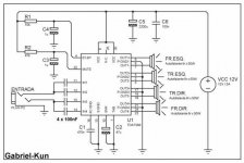
HI! I'm a rookie on electronics, but I love audio and decided to build a simple amplifyer and this one lokes simple and cheap...
I bought all the stuff and mount it on a protoboard.. How can I test the TDA? the circuit doesn't makes any sound... Who can help me???
How to test the circuit?
Thanks")
I bought all the stuff and mount it on a protoboard.. How can I test the TDA? the circuit doesn't makes any sound... Who can help me???
How to test the circuit?
Thanks
jorge_rc said:How can I test the TDA?
That is the datasheet application, so it should work, if everything is done correctly and the IC is not broken.jorge_rc said:How to test the circuit?
- - Compare if all connections are made correctly
- Check if all solder joints are well done. Resolder them, if you are not sure.
- Check the supply voltage and polarity. Must be above 7,5, better 8 V.
- Check the voltage at mute and standby pins. Must be above 3,5 V.
What means do you have to test? Multimeter? Oscilloscope? Frequency generator or CD with test signals? PC soundcard? Power resistors? Set of cheap test speakers?
The normal way is to either connect a cheap speaker or some power resistors to the output. Then feed a test signal to the input and measure along the signal path until where the signal goes. If you use a multimeter, try a test signal below 150 Hz. That is, where multimeters work best. On the other hand don't use too low frequency with too small test speakers.
With a 3,5 mm connector as in the schematic, it is not uncommon to have a bad connection already there.
If you post photos, somebody might be able to spot obvious faults.
Hey..
I build the circuit on a breadboad and I already check it 3 times and I had already also re-build it... to test, I only have a multimeter and it is one of the cheapest ones...
My power supply were taken from a pc an it is working well... I'm using 12v output.
I use a speaker with 10W, and it is also working well... but would ir be necessary to use 4 speakers???
Abou the jack, it is ok. i connect thee speaker and it sound almost like a headphone, but it makes a sound...
On friday I'll check that voltages.
Thanks
Hi.
Sorry to "dig up" this topic, but i think that is not necessary to create another on.
I have assembly a amp based on TD7386, follow a schematic like this, connected the St/By and the mute directly to the VCC, but with the resistors and capacitors.
But my problem is that when i connect the power source i hear a loud "bummp", and when turn off i hear that sound too.
What can i make? Connect a capacitor between power source and St/By and mute, to make them turn after the VCC?
Best Regards
ByB
ByBpt, you need to use a delayed relay to fix the problem.
Jorge, you have annihilateed the IC as soon as you turned on the PC psu.
When turning on, those things overshoot the voltage, to a level that the IC can not handle.
Next time just try using a battery and test what You have made.
You can, how ever with a bit of work use a pc psu.
It need dummy loads on its rails, and you allso need delayed relay to connect the amplifier to the 12 volt rail.
ByBpt, you need to use a delayed relay to fix the problem.
Hi.
Thanks for the help.
Ok that way will solve the bump when turning on, but when turning off, will that desapear too?
Best Regards
ByB
- Status
- This old topic is closed. If you want to reopen this topic, contact a moderator using the "Report Post" button.
- Home
- Amplifiers
- Chip Amps
- Help with TDA7386