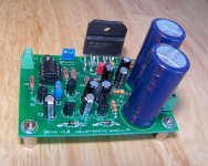
So I had some prototype boards made, populated them and have been listening to them for over a week. It sounds fantastic. Compared to the bridged LM4780 I was using prior, which has an input DC blocking capacitor only, it sounds better. The bass goes lower, and louder. The high range has lost some harshness, but hasn't lost any of the clarity. I'm using the same power supply, which was set up for 115 Wpc with the LM4780 bridged, and gives only about 30 Wpc with this design.
There is less than 2 mV DC on one channel (my equipment can't read it), but 19 mV DC on the other. I'm wondering if I may have made a bad solder joint, because I feel that's a little high. There is about 4 mV of noise at about 71,500 kHz, and about 2 mV at 625 kHz (with the inputs grounded).
There is less than 2 mV DC on one channel (my equipment can't read it), but 19 mV DC on the other. I'm wondering if I may have made a bad solder joint, because I feel that's a little high. There is about 4 mV of noise at about 71,500 kHz, and about 2 mV at 625 kHz (with the inputs grounded).
Attachments
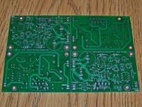
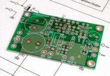
Thanks! I ordered them from http://www.batchpcb.com/. It's a hobby prototype service that waits until a "panel" is filled by smaller orders, then orders the production. Time from order to receipt is about 4 weeks. Cost is $10 + $2.50 a square inch, so it's a good deal for smaller items.
It sounds fantastic. Compared to the bridged LM4780 I was using prior,
Nice board!
Are you aware of that the LM4780 is two LM3886 chips in the same package?
http://home.pacific.net.au/~gnb/audio/lm4780.html
Yes, it's with the servo operating. The one probably is <1mVdc, but my meter only goes down to 1mVdc +/- 1mVdc, which is why I said <2mVdc. The other one still seems to be doing it's job. I can affect the DC offset by changing the volume pot with a source that has DC on the output, and watch the DC on the amp move, then recenter on the same value. It's probably less than 19mVdc. My meter reads it as 10mVdc, but my scope reads it as higher.
Thanks peranders. Yes, I was aware of that. It's the only chipamp I have heard to compare it to. The main difference, aside from not being bridged, is that there is no input capacitor on the new board. This time I used the 220pF cap across the + and - inputs to the LM3886, as it's the only bandwidth limiting feature in the design, and I didn't want to risk oscillations. So it's quite a bit different design, but the (almost) same chip for an interesting comparison.
Thanks peranders. Yes, I was aware of that. It's the only chipamp I have heard to compare it to. The main difference, aside from not being bridged, is that there is no input capacitor on the new board. This time I used the 220pF cap across the + and - inputs to the LM3886, as it's the only bandwidth limiting feature in the design, and I didn't want to risk oscillations. So it's quite a bit different design, but the (almost) same chip for an interesting comparison.
Thanks! I ordered them from http://www.batchpcb.com/. It's a hobby prototype service that waits until a "panel" is filled by smaller orders, then orders the production. Time from order to receipt is about 4 weeks. Cost is $10 + $2.50 a square inch, so it's a good deal for smaller items.
awesome!
omitting RF attenuation is a far worse crime than the very slight effect it may have on the extreme treble response if properly applied.you should use a scope to observe the output wave,then judge if the 220p cap is needed.
Usually,the 220p cap is a bane for the sound.
I remember that the 21.5 times gain make the unit unstable,try 25 time gain.
the 3886 should only be used at gain of >=10times. National tell you that in their literature.
The usual range of gains adopted is between 20times and 30times.
There is likely to be a small sound quality difference within this range. Tune the gain to suit your preferences of sound qulaity and needed gain/attenuation.
Unstable should NOT be a problem for a gain of 21.5times (+26.6dB) and 1.3dB of extra gain (25times, and an extra 1.3dB of attenuation to ensure listening SPLs are the same) should make an only just audible difference to some very discerning listeners. I doubt I am in that category.
Last edited:
As far as RF attenuation, I did not use it on my last build, which was a purchased PCB. This time I did. The sound is way better even with the 220pF cap, so I'm not considering removing it.
On the other hand, what would I see on a scope to tell me if the 220pF cap is needed or not?
As far as stability goes, I'm using the gain in the example circuit. Not because it was in the example circuit, but because it is the gain I want for the source output levels I have. I'm assuming from what I've read it would be really obvious if the amp wasn't stable, but how would I detect that?
if the gain is >+26dB then the chance of a good PCB assembly becoming unstable is very low.
But you can examine the input and output waveforms of various squarewave signals and see if the output is a good copy of the input. Changing gain may show significant differences in these output copies.
But you can examine the input and output waveforms of various squarewave signals and see if the output is a good copy of the input. Changing gain may show significant differences in these output copies.
So I borrowed an analog signal generator that does sine and square waves, but only up to 100kHz. When testing with sine waves, the output level is the same from 1Hz to 20kHz, then it slowly increases to approximately double at around 60kHz and stays at that level until 100kHz. Does this sound right? I'm having trouble finding exactly how to test / what to look for.
Last edited:
Do you have a speaker output zobel?
*You can "weaken" its values if you don't like the effect on sound; therefore, less effective zobel is much better than omission.
**If the resistor gets hot, the amp is oscillating (this doesn't necessarily require a scope).
***Because of the crazy looking resistor figure in the datasheet, one can tell that the cap is to be a lossy (cheap) polyester cap for speaker zobel. Increase the resistor value to 6.8R or higher figure if a different type of cap is used.
Do you have an output inductor//resistor combo?
Usually, this has a lovely effect on sound, and/or is at least unharmful.
Its fairly easy: Inductor, 10 turns around a pencil, and resistor is a 3w 10R. These are in parallel with each other as a unit piece and this unit is in series with the speaker jack. See the datasheet.
Do you have a small value ceramic cap (330pF? 220pF? 100pF?) between the chip's + and - inputs?
*smaller value is less effective and likewise has a lesser effect on sound; therefore, smaller value is much better than omission.
Got a ground loop buster between main star ground and the ground lug of a 3 prong power cord?
*There are many reports of beneficial bass and or tighter speaker control with good grounding; but, of course that does vary somewhat by individual application. One would expect the largest effect on the "gainclone" styles because. . .
**The groundpoint of the speaker (somewhere between power supply 0v versus the potentiometer ground) varies factors like "forwards" "bass" "noise" and "dynamics" by a considerable amount--basically its the difference between the workload of the amplifier's local power caps (which effect will get amplified) versus the workload of the caps aboard the power supply (which are more steady).
LM3886's, in my experience, aren't an exemplary example of stability. They're a bit nervous and seem to need some care. Datasheet illustrates distortion rising with frequency. But, there's no need of its amplification operable range exceeding the audio band by so far as it, likewise, has no need of doing any extraneous non-audio work.")
P.S. Both the output zobel and the output inductor//resistor can be located at the speaker jack for convenience (if they won't fit on the board).
*You can "weaken" its values if you don't like the effect on sound; therefore, less effective zobel is much better than omission.
**If the resistor gets hot, the amp is oscillating (this doesn't necessarily require a scope).
***Because of the crazy looking resistor figure in the datasheet, one can tell that the cap is to be a lossy (cheap) polyester cap for speaker zobel. Increase the resistor value to 6.8R or higher figure if a different type of cap is used.
Do you have an output inductor//resistor combo?
Usually, this has a lovely effect on sound, and/or is at least unharmful.
Its fairly easy: Inductor, 10 turns around a pencil, and resistor is a 3w 10R. These are in parallel with each other as a unit piece and this unit is in series with the speaker jack. See the datasheet.
Do you have a small value ceramic cap (330pF? 220pF? 100pF?) between the chip's + and - inputs?
*smaller value is less effective and likewise has a lesser effect on sound; therefore, smaller value is much better than omission.
Got a ground loop buster between main star ground and the ground lug of a 3 prong power cord?
*There are many reports of beneficial bass and or tighter speaker control with good grounding; but, of course that does vary somewhat by individual application. One would expect the largest effect on the "gainclone" styles because. . .
**The groundpoint of the speaker (somewhere between power supply 0v versus the potentiometer ground) varies factors like "forwards" "bass" "noise" and "dynamics" by a considerable amount--basically its the difference between the workload of the amplifier's local power caps (which effect will get amplified) versus the workload of the caps aboard the power supply (which are more steady).
LM3886's, in my experience, aren't an exemplary example of stability. They're a bit nervous and seem to need some care. Datasheet illustrates distortion rising with frequency. But, there's no need of its amplification operable range exceeding the audio band by so far as it, likewise, has no need of doing any extraneous non-audio work.
P.S. Both the output zobel and the output inductor//resistor can be located at the speaker jack for convenience (if they won't fit on the board).
I do not have any output networks at all. Output goes to the feedback network and the speaker.
I have a 220pF cap across the + and - inputs.
I have no ground loop breaker, as I've never had any hum at all (measured with the scope, the only noise I have is at or above 71kHz).
These are all design decisions I made. The amp never gets hot, even when I push it as I have a large heatsink and power supply voltage limits output to 30W per channel.
Note that the testing I did above with the function generator was with nothing connected on the output. Do I need a load for this type of test?
- Status
- This old topic is closed. If you want to reopen this topic, contact a moderator using the "Report Post" button.
- Home
- Amplifiers
- Chip Amps
- LM3886 Servo Design