I'm building the gainclone based project from ESP which includes an NE5532 preamp operating at +/- 15V before the LM3886. This will be a stereo chip amp with two LM3886 chips.
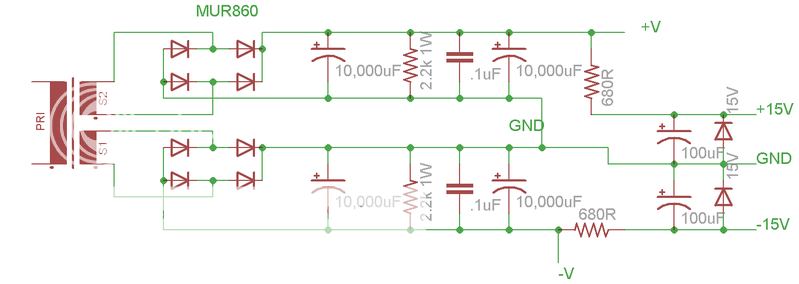
The PSU i've designed here is a mix between the psu from the ESP project, and the version from chipamp.com which is based on carlosFM's psu.
I just wanted to make sure everything looks good before I go any further. Primary input and secondary output will be fused. Transformer will be the Apex JR. 2X28V, 150VA, or the AntekInc AN-2225, 2X25V, 200VA.
So, all is well? Thanks for any suggestions,
Michael
I would add another .1uf bypass cap so each 10000uf cap has one each. I would also added one parrallel to the 100uf cap. Place the main fuse before the transformer. I recommend placing a fuse at the V+ and V- outputs too, as this will stop damage to the amp if the polarities are reversed.
An indicator LED is also very usefull in my opinion.
That 680ohm resistor will get hot so be aware of that
An indicator LED is also very usefull in my opinion.
That 680ohm resistor will get hot so be aware of that
I'd place a low value power resistor (say 0.22-0.5 ohm/5W) between the two 10,000uF caps to form a C-R-C filter.
Also, better in that case to reduce the size of the first cap to reduce charging current spikes and make the second cap larger to increase the RC filtering effect.
I'd suggest 6,800uF - 0.22-0.5 ohm - 2 x 6,800uF.
Also, better in that case to reduce the size of the first cap to reduce charging current spikes and make the second cap larger to increase the RC filtering effect.
I'd suggest 6,800uF - 0.22-0.5 ohm - 2 x 6,800uF.
Bleeders with a higher power rating would be good. Use a safety rating of 25 % for the transformer output voltage. That takes into account that your mains voltage may 10 % above nominal, and the regulation of an average transformer.
((25 V * 1,25 safety margin) - 1,4 V diode drop) * 1,41 no-load conversion factor = 42,1 V (Limit for the LM3886. Too much for the LM3875.)
P = 42,1 V * 42,1 V / 2200 Ohm = 0,81 W (Hot.)
((28 V * 1,25 safety margin) - 1,4 V diode drop) * 1,41 no-load conversion factor = 47,4 V (Too much for all Overture ICs, so don't use the 28 V transformer)
P = 47,4 V * 47,4 V / 2200 Ohm = 1,02 W (Too hot!)
The resistors should not operate at more than 50 % of their power rating under normal conditions. At 100 % they usually heat up to 125-150 °C. 2 W rating is better with good air circulation around them, and even 5 W would not be too much, if you have the space for it or if there is little fresh air flow around.
some usefull info -
carlosfm's design:
http://www.diyaudio.com/forums/showthread.php?s=&threadid=43423
National applications note on audio psu which is basicly the same as carlosfm's layout with other parts added to it.
http://www.national.com/an/AN/AN-1849.pdf
a commercial kit :
http://www.quasarelectronics.com/kit-files/smart-kit/1217.pdf
Hi,
what's your mains supply voltage tolerance?
What exactly is Apex selling?
110:28Vac or 115:28Vac or 120:28Vac, 150VA.
What is the 150VA transformer regulation?
Now, calculate the worst case DC supply voltage. Hint: you'll need 50V smoothing caps.
Once the amps are running with the quiescent current, the voltage will fall. What voltage do you expect in normal conditions?
Using a 28Vac transformer may be tolerable with a 3886 that is well cooled and drives a moderate reactance 8ohm speaker. But the chip will dissipate a lot of heat and will be near it's thermal and SOA limits.
Do not consider severe reactance 8ohm, nor moderate 6ohm nor any 4 to 8ohm and most definitely not 4ohm.
Finally, high efficiency speakers suit chipamps better than asking the chipamp to deliver high currents into low or medium efficiency speakers. Aim for >90db/W/m AND >=8ohm.
thanks for all the information guys, especially the power equations.
I'm going to go with an Antek 300VA, 2X22VAC toroid, and if I want to later I might pick up a 25VAC toroid to see which I like better. I'll get everything situated first with the 22VAC.
I plan on driving some JBL Century 100's I've got around. I think between 6-8ohm and from what I've read around I think they're about 90db sensitivity.
So I'll be increasing the wattage on the power resistors, and fusing the line input and V+/- outputs. Thanks again guys!
Michael
Hi,
use T fuse (= time delay = anti surge) on the mains side.
Use F fuses after the main smoothing caps. Size/value ~=50%peak output current on sinewave signal into nominal resistive load. Quasi says 50% of max. rms current. i.e. +-31Vdc & 6ohm speaker requires F2A or F2.5A on each supply rail.
use T fuse (= time delay = anti surge) on the mains side.
Use F fuses after the main smoothing caps. Size/value ~=50%peak output current on sinewave signal into nominal resistive load. Quasi says 50% of max. rms current. i.e. +-31Vdc & 6ohm speaker requires F2A or F2.5A on each supply rail.
- Status
- This old topic is closed. If you want to reopen this topic, contact a moderator using the "Report Post" button.
- Home
- Amplifiers
- Chip Amps
- My LM3886 PSU. Good?