well, here's my problem, i've recently built a lm3886 single ended configuration, power supply seems to be ok, i'm getting 25 and -25 volts at the power supply, when i test it for the first time, i'm having a 20v dc at the speaker terminal, help me guys, what do you think is the problem?
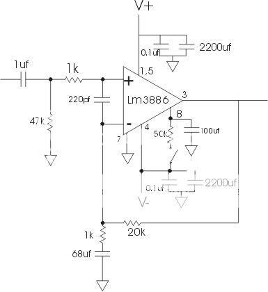
here is the schematic
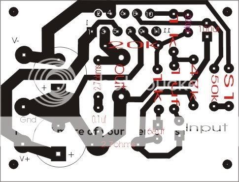
and the pcb layout
and a couple of pics
http://i171.photobucket.com/albums/u317/ryan750mhz/DSC02734.jpg
http://i171.photobucket.com/albums/u317/ryan750mhz/DSC02735.jpg
here is the schematic
and the pcb layout
and a couple of pics
http://i171.photobucket.com/albums/u317/ryan750mhz/DSC02734.jpg
http://i171.photobucket.com/albums/u317/ryan750mhz/DSC02735.jpg
impsick said:whats your negative input doing? im not the best to answer this but there may be a problem somewhere in that area. I dont know is the 2.7r needed? Dont quote me but i think there may have been a short from the input area.
THe 2.7R between grounds is just to isolate signal ground and power ground to prevent ground noise. The 220pF between + and - is just to suppress RF noise at the input causing a problem.
Really, the +ve input resistor to ground (47K) should be the same as the feedback resistor (20K) but it wouldn't cause 20V of output offset. I use 22K for both in my own design. My -ve feedback capacitor is 22uF compared to your 68uF but again, that shouldn't cause a big problem.
Your soldering is a little messy. At a guess, the problem is going to be there. Is the chip getting hot with input shorted to ground? If so it's probably oscillating, or dead.
thanks for the reply guys,
@andrew thanks, later if have time im going to measure the voltages on that area.")
i have a thought of the chip being dead,
the first time i plug this chip to the power supply, the power supply is unplugged but the capacitors is charged, and i think that the output speaker wires is touching one another. could this kill the chip??
@andrew thanks, later if have time im going to measure the voltages on that area.
i have a thought of the chip being dead,
the first time i plug this chip to the power supply, the power supply is unplugged but the capacitors is charged, and i think that the output speaker wires is touching one another. could this kill the chip??
Yes, the output leads would discharge the smoothing caps.ryan750 said:......... the power supply is unplugged but the capacitors is charged, and i think that the output speaker wires is touching one another. could this kill the chip??
Remember that the current for the amplifier output comes from the smoothing capacitors.
The transformer is there to recharge the capacitors.
No. With 1 % output they mean the output power for 1 % THD. With 0,25 V you should already be listening quite loudly, around a sixteenth of nominal output.ryan750 said:according to Overture design guide, i need a 1.024 Vrms input for 1% output, i've measured my input and it does not exceed 0.25V,
is this the problem?
Did you measure the input at the PCB input or at the ICs input pins? Follow the signal from pin to pin (but without producing shorts!) and see until where it goes. Same thing for the output.
The 20 V DC output from your former chip may have blown something else.
- Status
- This old topic is closed. If you want to reopen this topic, contact a moderator using the "Report Post" button.
- Home
- Amplifiers
- Chip Amps
- LM3886, 20v at output