
Sorry I was not clear enough....
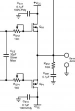
I was thinking about a cap after RGP1 and -VEE. this will do an RC filter ... and the fc will be 1/ (2 x pi x RGP1 x C)
Reference to this drawing :
http://www.diyaudio.com/forums/attachment.php?s=&postid=1824352&stamp=1241969879
Brgds - Gilles.
I was thinking about a cap after RGP1 and -VEE. this will do an RC filter ... and the fc will be 1/ (2 x pi x RGP1 x C)
Reference to this drawing :
http://www.diyaudio.com/forums/attachment.php?s=&postid=1824352&stamp=1241969879
Brgds - Gilles.
Hooray, I didn't kill the board - the power plug had come loose. 
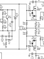
So I retried using 200ohms for Rg and still no luck with the ringing on the square wave. Inspecting it, it looks like its ringing at about 143kHz. I found a number of other oscillations looking at the noise floor. Hmmm. The search continues. I'm still wondering about those Rbo resistors - why aren't they used in AN-1850, when so many others use them?
So I retried using 200ohms for Rg and still no luck with the ringing on the square wave. Inspecting it, it looks like its ringing at about 143kHz. I found a number of other oscillations looking at the noise floor. Hmmm. The search continues. I'm still wondering about those Rbo resistors - why aren't they used in AN-1850, when so many others use them?
Also, I set the scope into XY mode, and compared the input to output, looking for phase shift. 20Hz showed some (I'd guess less than 20deg?), and then again some at 150kHz (maybe 30deg?). Would the shift around 150kHz have anything to do with the ringing at about 143kHz? Or with the LPF on the input of the LME chip, which is set to 130kHz?
cuibono said:...I'm still wondering about those Rbo resistors - why aren't they used in AN-1850, when so many others use them?
My guest is that they are there on the layout for test point purpose.... and/or maybe put zener diode there to limit the voltage during initial test to avoid destructing the expensive mosfets...
What values other use?
I think that the LME49810 for bjt has resistors there...
On my PCB - bought on the net - for LME49830 I have no Rbo resistors and it shows no sign of oscillation... but I use LAteral mosfet - I did not use the vertical ones.
Thanks for your input! I've been looking at a lot of other LME chip family designs, and they almost always have resistors between the the gate drive lines (even the LME49830 pdf has them - often the value is around 12k total). Interesting that yours don't. Where did you get them?
cuibono said:Thanks for your input! I've been looking at a lot of other LME chip family designs, and they almost always have resistors between the the gate drive lines (even the LME49830 pdf has them - often the value is around 12k total). Interesting that yours don't. Where did you get them?
The schematics I have from http://www.chp-pcb.cn/ has protection diodes (zener in series with 1N4148) instead of the 12k resistors. This schematics is propriatery of this company so I suppose I can not put it here. This is standard practice to protect mosfet. However, this web site is off-line since a few days...
So I've tried a number of things: I heated and pulled off all the copper on the pcb that was filling unused space. Tested that. Then I cut off the output section and re-did it point to point on the heatsink. Tested that. The results? No difference in the square wave ringing. So I doubt the layout has anything to do with it.
I tried adding 6.8k resistors in the Rbo positions - didn't do anything.
I tried different values of compensation caps (going from 20pF to 22 then 27). Didn't do anything.
What else could I try?
I tried adding 6.8k resistors in the Rbo positions - didn't do anything.
I tried different values of compensation caps (going from 20pF to 22 then 27). Didn't do anything.
What else could I try?
Panson was developing PCBs for that series of amps.
Ask.
http://www.diyaudio.com/forums/chip-amps/143163-comparing-lme49810-49830-49811-a.html#post1814571
Ask.
http://www.diyaudio.com/forums/chip-amps/143163-comparing-lme49810-49830-49811-a.html#post1814571
- Status
- This old topic is closed. If you want to reopen this topic, contact a moderator using the "Report Post" button.
- Home
- Amplifiers
- Chip Amps
- 6 channel LME49830 power amp