Well, how about this:
"The input sensitivity for this amplifier is 1.37V, resulting in an
output power of 175W at 0.1% THD+N into 8Ω running off of
±60V power supply rails." (the gain is 28.3V/V)
How did they get 175W? In the previous section, they had said the worst case power dissipation for a +/-60V supply working into 8ohms was 91W (see table 1 of an-1850). How does that work?
And the 1.37V is a rms value, correct?
Cheers
cuibono said:
How did they get 175W? In the previous section, they had said the worst case power dissipation for a +/-60V supply working into 8ohms was 91W (see table 1 of an-1850). How does that work?
And the 1.37V is a rms value, correct?
Hi,
You are confusing dissipation with power output. The 175 Watts is what the amp is able to supply to an 8 ohm load. The 91 watts is the heat the output stage will be dissipating to produce that power.
For example: If you have 2 output devices, one per side, they will be burning off ~45 watts each at maximum power output. If you have 4 output devices, 2 per side, they would each dissipate ~23 watts at max power output. This is heat that the heatsink needs to get rid of.
Yes the 1.37V is rms so about 3.9Vpp.
cuibono said:Thank you!
How did they get the 175W? When I multiply 1.37 by 28.3, square it and divide by 8, I get 188W. Just a little different...

Losses. Remember the heat being used up by the outputs? There is no such thing as perfect efficiency.
cuibono said:Lets do a little off the cuff power dissipation estimation...
from the an-1850 pdf:
PD(AMP)MAX = VCC^2/(2pi^2RL)
where Vcc is the sum of the + and - rails (guessing 108V for my case) and RL is the resistance of the load, lets assume 8ohms. The modules have four devices total, and the above equation gives 74W total power dissipation, each device sees about 18.5W.
My woofer will be about 4 ohms, which gives total power dissipation of 148W and 37W per device. Not bad if you derate the devices to 90W max for SOA.
There are a few things I don't understand. Is this calculation for a signal swinging to the rails? Isn't power dissipation higher with the signal at about half the rail voltage?
That formula is a formula for "The output stage’s worst-case maximum power dissipation for purely resistive loads" so it is the dissipation for a sine of about half power (about 2/3 max voltage) which is worst case. With music power dissipation will be lower than the 150W you calculated though.
There is a signal which gives even worse power dissipation: half voltage square wave. Power dissipation for this waveform is (Vrail/2)^2 / R. Vrail = voltage of a single rail. It is about 180W for 54V rails and 4 ohm load. I usually calculate this instead, gives almost the same value but is much simpler.
Lets calculate total quiescent power dissipation. The woofer will be biased at about 100mA - would this give 10.8W loss with no signal? The tweeter I plan on biasing up to 1A, so I guess the power dissipation will be 108W total. How's that sound?
So for the tweeter module working into 8 ohms, does the 108W of quiescent power loss add to the 74W of max power loss, meaning each device will possibly be seeing 45.5W power loss at maximum?
The formula that gave 74W assumes no idle current and it isn't as easy as them adding or that it's the highest one. But the latter one is a good approximation. Especially for a tweeter amp about 108W is what will be dissipated for that bias.
The other thing I don't understand is how changing the number of devices changes the power dissipation - it seems like fewer devices would lead to less power available and therefore less power dissipation, but the above equation doesn't factor it in. Seems like the power dissipation per device would actually be higher. I was hoping that using fewer devices on the tweeter module would help compensate for biasing it higher, but it looks like it will just make them blow faster..
It won't change if the rail voltage, load impedance and total bias kept the same. What will happen is that if you use too few devices they will be underrated and possibly blow up. 1 pair dissipating total 108W average is probably a bit optimistic, I'd probably use 2 pairs if it is IRFP250-like devices but it depends on what heatsink temperature is used and what mounting is used.
Thank you both!
Sounds like I'm ready to go. My only reservations at this point are, one, the tweeter and mid don't need 175W each, that would kill them; two, this amp is current limited way before I could reach the maximum power output for six channels running off one transformer. But in reality, I think it will work out quite well. Also, 29dB gain might be too much, considering my source has 5.6Vpp output, but that is easily fixed.
Cheers,
Patrick
hi everybody!
sorry for my english but i'm french so be comprehensive please...
i'm building a project as yours actually.
link
I've already done routing and the pcb are working but:
I have a problem with Vbias adjustment.
In the AN1850, they use couple of resistors and a bd139 to do thermal adjustment. When I use these components I obtain a Vbias arounf 2.5 or 2.6V The trimmer doesn't change anything. Unfortunately the IRFP240 and 9240 I use need around 4V to conduct perfectly so i have distortion.
If the bd139 not mounted and the adjustable is around 3k the amp works fine and the Vbias adjusts normaly, but if the bd is on board, there is 2.5V even if I change resistor values.
Do you have any pproblems with this part of schematics? What are your values? I don't understand very well how it works...
many thanks!
Sorry rockeurfoo, I'm going straight by the application notes. Good luck sorting it out, it can be frustrating.
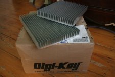
I got my heatsinks yesterday, and my digikey order came today. The heatsinks are very nice - smooth, clean, and larger than I imagined. Getting packages in the mail might be my favorite part of building stuff...
I got my heatsinks yesterday, and my digikey order came today. The heatsinks are very nice - smooth, clean, and larger than I imagined. Getting packages in the mail might be my favorite part of building stuff...
Attachments
As it turned out, the boards from the app. notes were not going to work for me, so I've had to redo them. Added some extra time, but they are better for it. I've got them stuffed, and am going to start testing them today or tomorrow. I'll post some pics soon too...
Here is a question I hope someone can help me out with - my power transformer has dual 120V primaries, and only a single set of secondaries. But the primaries aren't what I'm used to: they are labeled 0-100-120. I'm guessing I wire the two sets in parallel for 120V operation, right?
I'm excited to get this done because then I can do the real work - loudspeakers!
PS - I'll probably post all my eagle files and lme49830 library if everyone behaves!
I dunno, I might not post the board layout files. This thing is supposed to pass up to 1200W or so. Maybe I shouldn't make it easy for people to electrocute themselves. I am a little worried that the tracks are not thick enough - I used 1oz copper. The board overall is about 4" by 3". The longest power tracks are about 2.5" long by .15" wide...
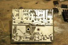
This board came out really clean when I did the toner transfer - probably the highest quality I've done yet. Unfortunately, the next board had tons of lifted traces...
This board came out really clean when I did the toner transfer - probably the highest quality I've done yet. Unfortunately, the next board had tons of lifted traces...
Attachments
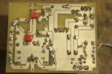
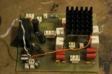
sorry this one is a little dark. I havn't soldered in the LME chip or the fets yet. This is my first amp board (of six). I'm gonna have to make the pads bigger and with greater clearance, I forgot to on this board. Like I said, my double sided boards are not quite as perfect as I'd like (yet). The dark thing in the middle is the LME's heatsink, which is just sitting there.
Attachments
I had a couple more questions I was hoping for help with:
In AN-1850, on page 5, in the section "output stage power dissipation", right after equation 4, it states "Given [4 constants] Results in Pd(ic) = 35.1W maximum average power dissipation per device de-rated for case temperature... The total average output stage power dissipation is 140.4W". On page four just under Table 1, it talks about how each device would have to dissipate 71W when driving a 4ohm load with 75V rails. So what I understand, is that the only way to drive more than 140W (for instance any 4 ohm load, look at Table 1 for examples), would be to reduce the C/W rating of the heatsink or increase the total number of output stages. Am I correct? Hope that makes sense.
The other question is with regards to the grounding scheme. Please refer to figure 4 of AN-1850. Figure 4 presents an optimal grounding scheme for the source, amplifier, power supply and speaker (load). There is something implicit to the drawing, and I'm not sure I have it right. The power supply, in the schematic, has an earth ground (the third pin of the power plug, see AN-1849), but all the circuitry is floating above it due to an 100ohm resistor. Is it implied that the source is earth grounded too? Doesn't this cause large ground currents to have to pass through the signal's ground connection? Or is the source not supposed to be connected to earth ground?
Much thanks before I toast something...
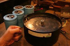
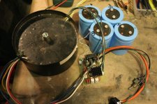
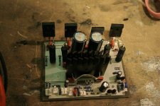
cuibono said:the almost complete power supply. I've got to admit I'm a little scared to plug it in. Thank goodness for fuses...
don't plug it in and hope.
Use a mains light bulb tester. It protects you , the equipment and your mains fuse.
And do it in stages.
Test the transformer wiring alone.
Add the PSU and test again.
Finally add the amplifier and test.
- Status
- This old topic is closed. If you want to reopen this topic, contact a moderator using the "Report Post" button.
- Home
- Amplifiers
- Chip Amps
- 6 channel LME49830 power amp